Tool turning device and turning method thereof

A technology of turning device and tooling, applied in the direction of transportation and packaging, conveyor objects, etc., can solve problems such as scratches, limited products, defects, etc., to improve production efficiency, flexibly turn over, and avoid scratches or defects.

Active Publication Date: 2015-08-19
GOERTEK INC
View PDF13 Cites 6 Cited by
  • Summary
  • Abstract
  • Description
  • Claims
  • Application Information

AI Technical Summary

Problems solved by technology

[0003] In view of the above problems, the object of the present invention is to provide a tooling turning device and its turning method

Method used


Image

  • Tool turning device and turning method thereof
  • Tool turning device and turning method thereof
  • Tool turning device and turning method thereof

Examples


Embodiment Construction

[0023] Specific embodiments of the present invention will be described in detail below in conjunction with the accompanying drawings.

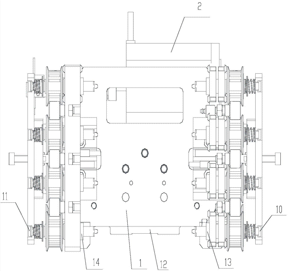
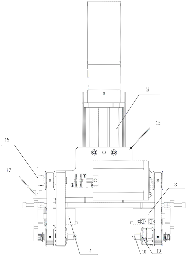
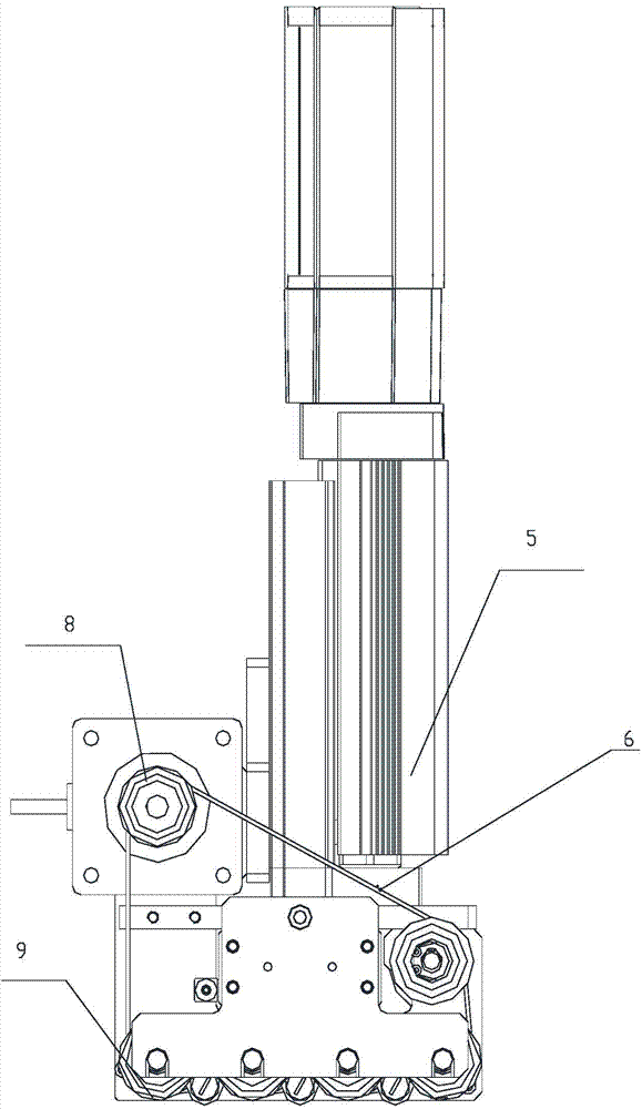
[0024] In view of the limitations of the aforementioned existing tool turning device on the turning of electronic products, the present invention can turn the product positioning tool over any angle through the provided rotating mechanism, the driving mechanism driving the rotating mechanism, and the tool clamping mechanism connected to the rotating mechanism. Therefore, the flexible turning over of the product is realized; and at least two toolings to be turned over can be turned over at the same time, thereby improving the production efficiency.

[0025] In order to further illustrate the tooling turning device provided by the present invention, figure 1 , figure 2 and image 3 The first, second and third structures of the tool turning device according to the present invention are respectively shown. Such as Figure 1 to Figure 3 Shown:...


PUM


Abstract

The invention provides a tool turning device and a turning method thereof. The tool turning device comprises a rotating mechanism, a driving mechanism for driving the rotating mechanism to rotate, a tool clamping mechanism connected with the rotating mechanism and a fixing plate, wherein the driving mechanism, the rotating mechanism and the clamping mechanism are all fixed to the fixing plate through bolts, the rotating mechanism can be driven by the driving mechanism to drive the tool clamping mechanism to clamp and lift tools to be turned, and the driving mechanism can drive the rotating mechanism to turn the tools to be turned. By means of the tool turning device, product locating tools can be turned at any angle, products can be flexibly turned, and the producing efficiency is improved.

Description

technical field [0001] The invention relates to the technical field of manufacturing and processing of electronic products, and more specifically, relates to a tool turning device and a turning method thereof. Background technique [0002] For the production process or the processing needs of the product itself, it is sometimes necessary to flip the product. At present, in the case of flipping electronic products, the flipping is usually realized by directly clamping or sucking the product. However, for some products with high requirements or irregular shapes, it is not suitable to use the clamping or suction method, and, in the process of turning over, the above-mentioned method is easy to cause scratches to the product, which is very important for precision electronic products. As far as it is concerned, it may affect the quality of the product, and then there will be defective products. Therefore, the flipping of the electronic product realized by the direct clamping or...

Claims


Application Information

Patent Timeline
IPC IPC(8): B65G47/252
Inventor 杨强
Owner GOERTEK INC
Why Eureka
Try Eureka