Bearing holder

A bearing seat, bearing technology, applied in the direction of bearing components, shafts and bearings, rigid brackets of bearing components, etc., can solve the problems of inconvenient movement and temporary use, etc.

Inactive Publication Date: 2015-08-19
XINCHANG HUAXIONG MACHINERY
View PDF0 Cites 0 Cited by
  • Summary
  • Abstract
  • Description
  • Claims
  • Application Information

AI Technical Summary

Problems solved by technology

[0002] The bearing seat is a widely used mechanical part, but the existing bearing seats are all processed on the shell or frame of the corresponding part, which is inconvenient to move and temporarily use

Method used


Image

  • Bearing holder

Examples


Embodiment Construction

[0008] Below in conjunction with accompanying drawing, the present invention will be further described:

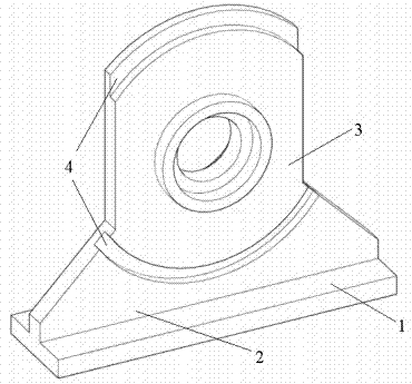
[0009] As shown in Figure 1, a bearing seat includes a base plate 1, a connecting plate 2 and a mounting plate 3, the base plate 1 is generally rectangular, the base plate 1 has a connecting plate 2, the connecting plate 2 is generally trapezoidal, There is a mounting plate 3 on the connecting plate 2, the lower end of the mounting plate 3 is connected with the connecting plate 2, and the left and right sides form an upwardly protruding arc with the vertical upper end of the substrate 1, and the center position of the mounting plate 3 has a bearing mounting hole. The mounting plate 3 and the connecting plate 2 form a plate-shaped whole, and there is an arc-shaped groove 4 below the bearing mounting hole on the plate-shaped whole. The arc-shaped groove 4 is concentric with the bearing mounting hole and has a rectangular cross section. .

[0010] The length of the lower bot...


PUM


Abstract

The invention relates to a bearing holder, which is characterized in that a substrate is rectangular, wherein a connecting plate is arranged on the substrate, the connecting plate is approximately trapezoid; a mounting plate is arranged on the connecting plate; the lower end of the mounting plate is connected with the connecting plate; the left and right sides of the mounting plate are perpendicular to the substrate; the upper end of the mounting plate is convex upwards to form an arc; a bearing mounting hole is formed in the central position of the mounting plate; the mounting plate and the connecting plate are connected to form a plate-shaped whole body; an arc-shaped groove is formed below the bearing mounting hole in the plate-shaped whole body and is concentric with the bearing mounting hole; the cross section of the arc-shaped groove is rectangular. The bearing holder has the advantage that by virtue of the independent substrate, the bearing holder can be arranged at a desired place at random and used at any time.

Description

technical field [0001] The invention relates to a bearing housing. Background technique [0002] Bearing housings are widely used mechanical parts, but the existing bearing housings are all processed on the housing or frame of the corresponding parts, which is inconvenient to move and temporarily use. Contents of the invention [0003] In view of the problems existing in the prior art, the purpose of the present invention is to provide a technical solution for a bearing seat. [0004] The above-mentioned bearing housing includes a base plate, a connecting plate and a mounting plate, and is characterized in that the base plate is rectangular, and there is a connecting plate on the base plate, and the connecting plate is generally trapezoidal, and there is a mounting plate on the connecting plate , the lower end of the mounting plate is connected to the connecting plate, the left and right sides are perpendicular to the base plate, and the upper end forms an upwardly protru...

Claims


Application Information

Patent Timeline
IPC IPC(8): F16C35/00
Inventor 俞玉华
Owner XINCHANG HUAXIONG MACHINERY
Why Eureka
Try Eureka