
Cam type limit folding mechanism for battery case
A battery casing and cam-type technology, which is applied in the field of cam-type limit folding mechanism for battery casings, can solve the problems of high use cost and maintenance cost, inconvenient use, complex structure, etc., and achieves convenient operation, simple structure, The effect of high production efficiency
- Summary
- Abstract
- Description
- Claims
- Application Information
AI Technical Summary
Problems solved by technology
Method used
Image

Examples
Embodiment 1
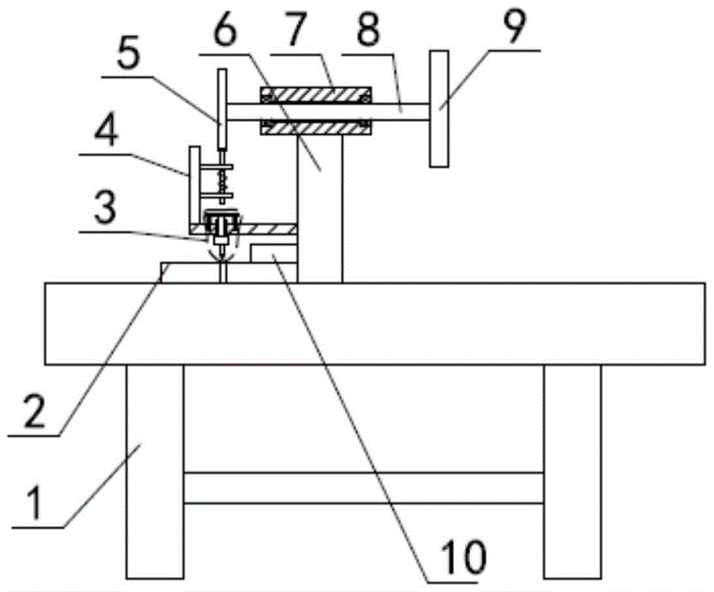
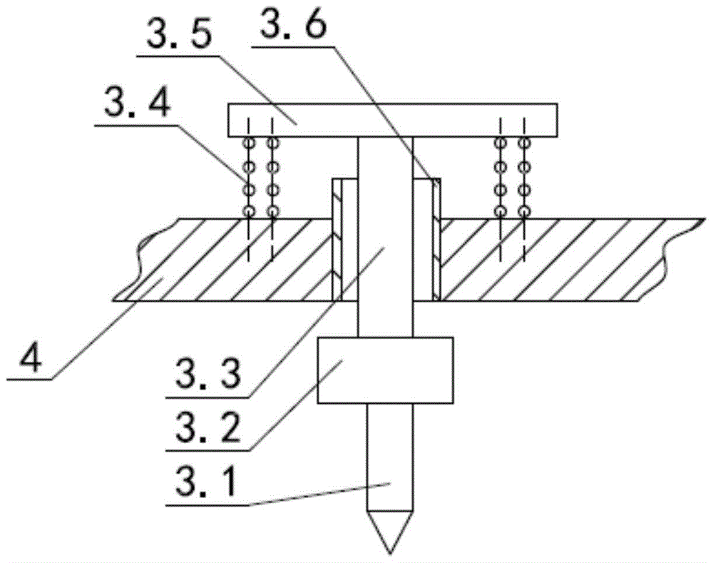
[0015] like figure 1 , figure 2 As shown, the battery casing uses a cam-type limit folding mechanism, including a workbench 1, on which a bottom mold 2 for folding is installed, and on the workbench 1 on the right side of the bottom mold 2, there is a vertically fixed installation Column 6, a casing 7 is installed horizontally on the mounting column 6, a rotating shaft 8 is installed horizontally on the casing 7, a handle plate 9 for rotation is installed on the right end of the rotating shaft 8, and the corresponding bottom mold 2 is provided directly above it. For the hemming reset mechanism 3 of the hemming, the hemming resetting mechanism 3 includes the mounting bracket 4 fixed on the mounting column 6, the hemming knife 3.1 and the transmission rod 3.3 for moving up and down, and the hemming knife 3.1 is installed on the The lower end of the transmission rod 3.3 is covered with a sliding sleeve 3.6 on the transmission rod 3.3, and the sliding sleeve 3.6 is mounted on th...
Embodiment 2
[0019] This embodiment is changed on the basis of the first embodiment, and the height of the workbench 1 is changed to 1000 mm. Others are the same as embodiment one.
Embodiment 3
[0021] This embodiment is changed on the basis of the first embodiment, and the height of the workbench 1 is changed to 1100 mm. Others are the same as embodiment one.
PUM
| Property | Measurement | Unit |
|---|---|---|
| height | aaaaa | aaaaa |
Abstract
Description
Claims
Application Information