Pneumatic conveyor

A technology of pneumatic conveying and rotating shafts, which is applied in the direction of conveying bulk materials, conveyors, transportation and packaging, etc. It can solve the problems of gas leakage, easy to hold shafts, large wear, etc., and achieve the effect of prolonged service life and continuous sealing

Inactive Publication Date: 2015-09-09
湖南省益能环保科技有限公司
View PDF10 Cites 0 Cited by
  • Summary
  • Abstract
  • Description
  • Claims
  • Application Information

AI Technical Summary

Problems solved by technology

[0003] 1. Because the gas is sealed by pipelines, and the material is transported by means of pneumatic vehicles or mechanical transport, due to the high pressure of the transported gas, the gas will leak along the material inlet when feeding, causing environmental pollution and gas pressure relief, which cannot be achieved the purpose of the delivery;
[0004] 2. At present, mechanical seals are widely used, such as air locks. The mechanical seal equipment wears a lot, has a short service life, and the sealing performance of the equipment is poor.
At the same time, the mechanical seal is a seal in motion. For materials with strong water absorption, poor fluidity, and high viscosity, they are easy to hold the shaft during motion, and continuous transportation cannot be achieved.

Method used


Image

  • Pneumatic conveyor

Examples


Embodiment Construction

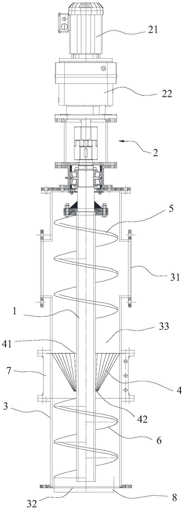
[0017] Below, in conjunction with accompanying drawing and specific embodiment, the present invention is described further:

[0018] Such as figure 1 The pneumatic conveying device shown includes a rotating shaft, a driving mechanism for driving the rotating shaft to rotate, a housing and an elastic sealing diaphragm, the driving mechanism is connected to the rotating shaft, and the rotating shaft seal is connected to one end of the housing , and the rotating shaft extends into the housing, the wall of the housing is provided with a material inlet, the rotating shaft facing the material inlet is provided with a feeding screw, and the other end of the housing is provided with a material outlet, A discharge screw is provided on the rotating shaft close to the discharge port, and the elastic sealing diaphragm is elastically sleeved on the rotating shaft between the discharging screw and the feeding screw and is sealed with the inner wall of the housing. A sealing zone is formed ...


PUM


Abstract

The invention discloses a pneumatic conveyor which comprises a rotation shaft, a drive mechanism used to drive inward rotation of the rotation shaft, a shell and an elastic sealing membrane, wherein the drive mechanism is connected to the rotation shaft by driving, the rotation shaft is sealed and passes through one end of the shell, the rotation shaft is stretched into the shell, a feeding hole is disposed in the wall of the shell, a feeding spiral is disposed on the rotation shaft right facing the feeding hole, a discharge hole is disposed in the other end of the shell, a discharge spiral is disposed on the rotation shaft near to the discharge hole, the elastic sealing membrane elastically sleeves the rotation shaft between the discharge spiral and the feeding spiral and is sealed and coordinated with the inner wall of the shell, and a sealing area is formed inside the shell between the elastic sealing membrane and the feeding spiral. The pneumatic conveyor provided by the invention can be suitable to various materials, does not need journal sticking during conveying and realizes the completely sealed continuous conveying without mechanism wear.

Description

technical field [0001] The invention relates to a gas conveying sealing device, in particular to a pneumatic conveying device used for shutting off air or mixing solid materials with airflow during gas conveying. Background technique [0002] At present, in the process of gas transportation of powder materials, there are mainly the following technical problems: [0003] 1. Because the gas is sealed by pipelines, and the materials are transported by means of pneumatic vehicles or mechanical transportation, due to the high pressure of the transported gas, the gas will leak along the material inlet when feeding, causing environmental pollution and gas pressure relief, which cannot be achieved the purpose of the delivery; [0004] 2. At present, mechanical seals are widely used, such as air locks. The mechanical seal equipment wears a lot, has a short service life, and the sealing performance of the equipment is poor. At the same time, the mechanical seal is a seal in motion. ...

Claims


Application Information

Patent Timeline
Patent Type & Authority Applications(China)
IPC IPC(8): B65G53/48
Inventor 冯本剑
Owner 湖南省益能环保科技有限公司
Why Eureka
Try Eureka