Hand-operated driving gear mechanism

A driving gear, hand-operated technology, applied in the direction of belt/chain/gear, transmission box, mechanical equipment, etc., can solve the problems of inconvenient rotating drive and inflexible control

Inactive Publication Date: 2015-09-09
赵静
View PDF5 Cites 2 Cited by
  • Summary
  • Abstract
  • Description
  • Claims
  • Application Information

AI Technical Summary

Problems solved by technology

The existing gears are inconvenient to rota

Method used


Image

  • Hand-operated driving gear mechanism
  • Hand-operated driving gear mechanism

Examples


Embodiment Construction

[0012] The preferred embodiments of the present invention will be described in detail below in conjunction with the accompanying drawings, so that the advantages and features of the present invention can be more easily understood by those skilled in the art, so as to define the protection scope of the present invention more clearly.

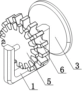
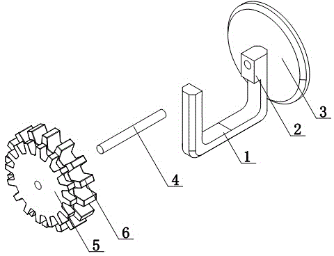
[0013] Such as figure 1 and figure 2 As shown, a hand-operated drive gear mechanism includes a bracket 1, a hand wheel 3 is provided on the side wall of the bracket 1, a driving shaft 4 is arranged inside the bracket 1, the driving shaft 4 is arranged horizontally, and the driving shaft 4 is set with a second A driving gear 5 and a second driving gear 6, the first driving gear 5 and the second driving gear 6 are arranged concentrically;

[0014] The manual drive gear mechanism of the present invention allows the user to control the hand wheel 3 to rotate, thereby controlling the first drive gear 5 and the second drive gear 6 to rotate through t...


PUM


Abstract

The invention discloses a hand-operated driving gear mechanism. The hand-operated driving gear mechanism comprises a support, a sidewall of the support is provided with a hand-operated wheel, a driving shaft is arranged in the support, the driving shaft is arranged in a horizontal manner, the driving shaft is equipped with a first driving gear and a second driving gear in a sleeved manner, and the first driving gear and the second driving gear are arranged in the manner of concentric circles. According to the hand-operated driving gear mechanism, users can control the hand-operated wheel to realize rotation, the first driving gear and the second driving gear are controlled to realize rotation via the driving shaft, and the rotation control of the gears is facilitated.

Description

technical field [0001] The invention relates to a gear mechanism, in particular to a hand-operated driving gear mechanism. Background technique [0002] There are teeth on the rim that can continuously mesh with mechanical elements that transmit motion and power. Gears are toothed mechanical parts that can mesh with each other, and the application of gears in transmission has appeared very early. The principle of generative gear cutting method and the emergence of special machine tools and cutting tools using this principle for gear cutting. The existing gears are inconvenient to rotate and drive, and the control is inflexible. Contents of the invention [0003] The present invention mainly solves the technical problems existing in the prior art, thereby providing a user can control the hand wheel to realize rotation, thereby controlling the first driving gear and the second driving gear to realize rotation through the driving shaft, thereby facilitating the gear alignm...

Claims


Application Information

Patent Timeline
IPC IPC(8): F16H57/02
CPCF16H57/00F16H57/02F16H2057/02026
Inventor 赵静
Owner 赵静
Why Eureka
Try Eureka