
A floor heating system

A heating system and floor technology, applied in the heating field, can solve the problems of continuous heating of indoor floors and slow defrosting speed, and achieve the effects of promoting and applying, increasing effective floor height, and simple structure

Inactive Publication Date: 2015-09-09
GD MIDEA HEATING & VENTILATING EQUIP CO LTD +1
View PDF5 Cites 3 Cited by
  • Summary
  • Abstract
  • Description
  • Claims
  • Application Information

AI Technical Summary

Problems solved by technology

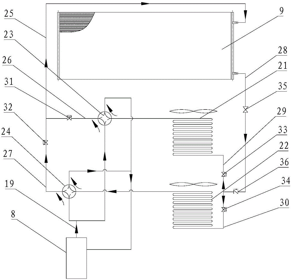
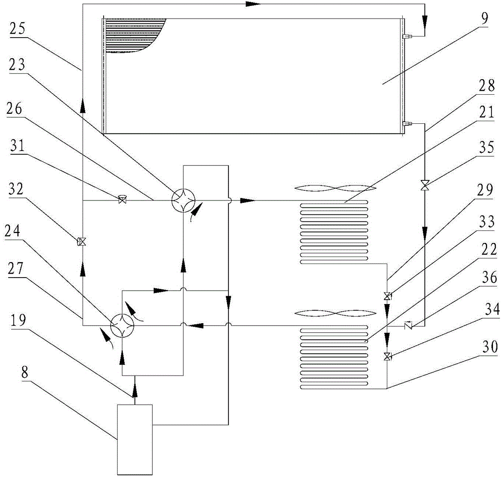
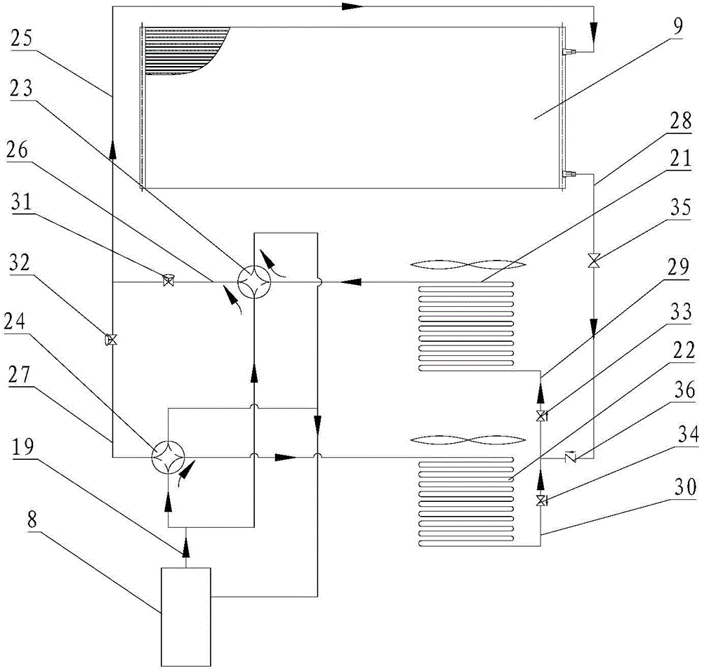
[0006] The technical problem to be solved by the present invention is that the existing floor heating system cannot continuously heat the indoor floor when defrosting, and the defrosting speed is slow

Method used


Image

  • A floor heating system
  • A floor heating system
  • A floor heating system

Examples


Embodiment Construction

[0034] Embodiments of the present invention will be further described in detail below in conjunction with the accompanying drawings and examples. The following examples are used to illustrate the present invention, but should not be used to limit the scope of the present invention.

[0035] In the description of the present invention, it should be noted that unless otherwise specified, the meaning of "plurality" is two or more; the terms "upper", "lower", "left", "right", "inner ", "outside", "front end", "rear end", "head", "tail", etc. indicate the orientation or positional relationship based on the orientation or positional relationship shown in the drawings, and are only for the convenience of describing the present invention and Simplified descriptions, rather than indicating or implying that the device or element referred to must have a particular orientation, be constructed and operate in a particular orientation, and thus should not be construed as limiting the inventi...


PUM


Abstract

The invention relates to the technical field of heating, specifically to a floor heating system. The floor heating system comprises an indoor unit, a compressor and a floor heating heat exchanger disposed in a floor. The outer door unit comprises at least two outdoor heat exchangers. Each outdoor heat exchanger is connected with the compressor and the floor heating heat exchanger to form an independent circulation loop used for conveying a refrigerant. When being used for defrosting of the outdoor unit, the floor heating system can provide heat indoors continuously and achieve the objective of rapid defrosting. The efficiency and reliability of the system are improved.

Description

technical field [0001] The invention relates to the technical field of heating, in particular to a floor heating system. Background technique [0002] At present, floor heating is one of the most popular and advocated heating methods in the world. This heating method makes the indoor surface temperature uniform, the indoor air temperature field distribution is reasonable, and the human body feels more comfortable. Therefore, along with the continuous improvement of living standards, more and more people begin to recognize and accept the mode of this ground heating. [0003] During the heating process of the floor heating system, frosting will gradually occur outdoors, while the existing conventional heating system needs to stop heating during the defrosting process, because only one set of circulation loops is running in this heating system, which needs to pass through four Turn the through valve to defrost the outdoor unit, which not only causes the floor heating heat exch...

Claims


Application Information

Patent Timeline
Patent Type & Authority Applications(China)
IPC IPC(8): F25B13/00F25B41/04F25B41/06F25B41/20F25B41/30
CPCF25B13/00F25B47/02F25B2347/02F25B2313/02742F25B41/30F25B41/20
Inventor 洪志荣
Owner GD MIDEA HEATING & VENTILATING EQUIP CO LTD
Learn More