
Energy storage heating device

A heating device and accumulator technology, applied in the heating field, can solve the problems of complex equipment, long cycle time, and power energy consumption, and achieve the effects of convenient operation, low cost, and simple structure

Active Publication Date: 2020-07-10
杭州轻巧科技有限公司
View PDF8 Cites 1 Cited by
  • Summary
  • Abstract
  • Description
  • Claims
  • Application Information

AI Technical Summary

Problems solved by technology

At present, although there are various heat storage methods using the principle of phase change energy storage, there are still many shortcomings and deficiencies in the actual use process. The sleeping time is in the bedroom, the eating time is in the kitchen or dining room, the living room is in the living room when receiving guests, the study room is in the reading room, and the bathroom is sometimes used, that is, the activity area of ​​people changes at different time periods. , and these existing energy storage heaters are not suitable for moving around in various rooms, that is, although the existing phase change energy storage heaters have the function of energy storage, they are unfavorable in quickly transferring energy. Traditional water circulation pipelines for heat transfer are not only slow, complex equipment, long cycle time required, and additional power energy is spent

Method used


Image

  • Energy storage heating device
  • Energy storage heating device
  • Energy storage heating device

Examples


Embodiment 1

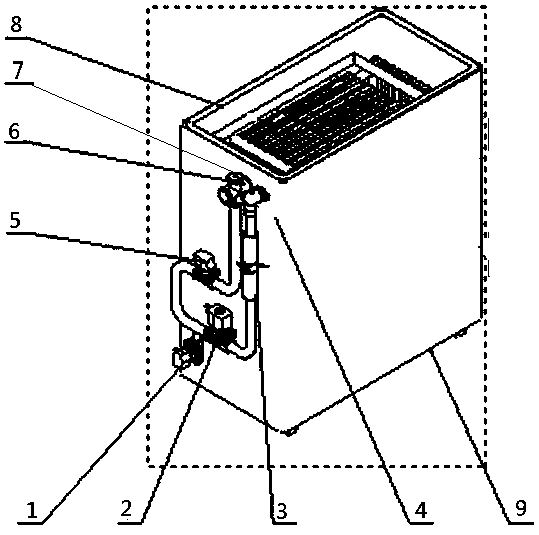
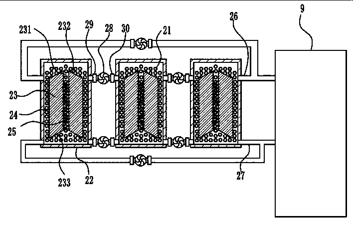
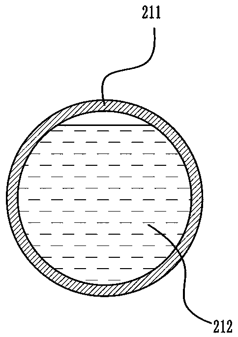
[0022] Such as figure 1 , 2 As shown in , 3, different from the foregoing embodiments, an energy storage heating device includes a heating source, a phase change accumulator, a phase change energy storage medium, and a radiator, and the phase change accumulator includes a thermal insulation layer 8, the heat preservation box 9, the radiator includes several heat dissipation boxes, the phase change energy storage medium is a round particle 21, and the particle has a closed elastic surface layer 211, such as a silicone rubber elastic film with good thermal conductivity . The elastic surface layer is wrapped with a phase-change energy storage medium, such as a phase-change energy storage paraffin liquid 212, and the particles are arranged in water in several heat dissipation boxes 22, and different heat dissipation boxes can be arranged in different rooms. There are counterweight fillers in the particles, such as iron powder, so that at a certain water temperature, the density ...


PUM


Abstract

The invention provides an energy storage heating device and relates to heating devices. Through the energy storage heating device, the problem that heat of a heating device in the prior art cannot bequickly transferred according to according to activities of people. The energy storage heating device comprises a heating source, a phase change energy accumulator, a phase change energy storage medium and a heat radiator. The phase change energy accumulator comprises a heat insulation box. The heat radiator comprises a plurality of heat radiating boxes. The phase change energy storage medium belongs to particles. Each particle has an enclosed elastic surface layer. The phase change energy storage medium is wrapped inside the elastic surface layers. The particles are arranged in the heat radiating boxes. The heat radiating boxes communicate with the heat insulation box through a water inlet pipe and a water outlet pipe. Particle conveying devices are arranged on the pipes. According to theenergy storage heating device, the phase change energy storage medium is creatively arranged in the particles so that a great deal of heat can be rapidly transferred to different spaces, the densityof the particles can change along with temperature changes, and the particles at high temperature are selectively conveyed into the spaces in need of heat.

Description

technical field [0001] The invention belongs to the technical field of heating, in particular to an energy storage heating device. Background technique [0002] At present, the vast rural areas and remote areas cannot effectively provide collective heating, causing a large amount of fossil energy to be directly used for heating without treatment, resulting in environmental pollution and waste of resources. Compared with the widely used air conditioning and electric heating in the market Equipment, because heat cannot be stored during use, resulting in increased use costs, increased heating costs for residents or enterprises, especially heaters without energy storage functions are inconvenient to use solar energy and other clean energy that can be used for a fixed period of time. Storing this energy during the day and releasing it at a specific time at night is a good option, both for the environment and for heating costs. [0003] In an increasingly energy-constrained socie...

Claims


Application Information

Patent Timeline
IPC IPC(8): F24D15/02F24D19/00F24D19/10
CPCF24D15/02F24D19/00F24D19/1006
Inventor 冯谢莲尹拂晓陈希章
Owner 杭州轻巧科技有限公司
Learn More