A Fully Engaged Claw Rotor Profile

A technology of rotor profiles and full meshing, which is applied in the direction of rotary piston pumps, rotary piston machines, components of pumping devices for elastic fluids, etc. Rotor sealing, stress concentration, etc.

Inactive Publication Date: 2016-10-05
CHINA UNIV OF PETROLEUM (EAST CHINA)
View PDF4 Cites 0 Cited by
  • Summary
  • Abstract
  • Description
  • Claims
  • Application Information

AI Technical Summary

Problems solved by technology

[0003] The meshing characteristics of the rotor profile directly determine the working performance of the claw rotor. The existing straight claw claw rotor profile includes: 3 sections of arc, 1 section of line, 2 sections of cycloid, and 1 section of envelope; However, the existing straight-claw-claw rotor profile has the following disadvantages: ① There are two cusps at the line segment connected to the arc of the claw top and the cycloid, and the mechanical properties of the rotor cusps are unstable and susceptible to damage. The scouring and impact of the fluid cause a large deformation; ②The existing straight-claw rotor has two sharp points meshing with the cycloid when it is working, so that the sealing effect is poor, so the medium meshes at the sharp point The leakage at the point is large, and it is easy to wear at the sharp point, which affects the performance and life of the claw rotor
[0004] Patent No.: The application document of ZL201110308963.4 proposes a claw-type rotor profile, which is a claw-type rotor composed of 5 arcs and 3 cycloids. This rotor realizes the smoothness of the addendum arc and other profiles. connection and the meshing of curves; but the shortcomings of the claw rotor profile are: ①There are sharp points at the joint of the pitch circle arc, which is not conducive to the sealing of the claw rotor and is prone to stress concentration; ②The left side The normal equidistant curve GH of the cycloid of the claw rotor and the normal equidistant curve gh of the cycloid of the right claw rotor do not participate in meshing

Method used


Image

  • A Fully Engaged Claw Rotor Profile
  • A Fully Engaged Claw Rotor Profile
  • A Fully Engaged Claw Rotor Profile

Examples


Embodiment Construction

[0043] The present invention will be further described below in conjunction with the accompanying drawings and embodiments.

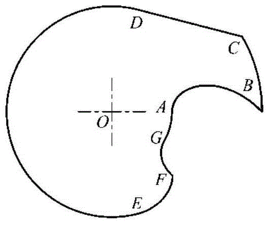
[0044] like figure 1As shown, the existing straight-claw-claw rotor profile is composed of 3 arcs, 2 cycloids, 1 line segment and 1 line segment envelope, starting from the cycloid in the counterclockwise direction: cycloid AB, claw top arc BC, line segment CD, pitch circle arc DE, envelope EF of line segment, cycloid FG, claw bottom arc GA; among them, two connection points B and C of claw top arc BC is a point that is not smooth, that is, a sharp point.

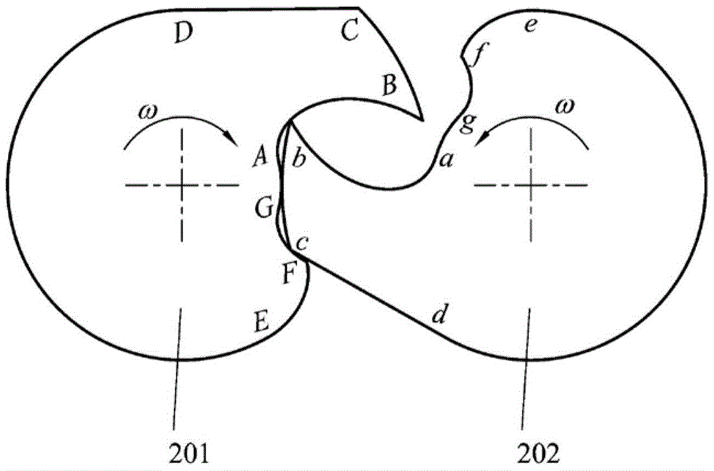
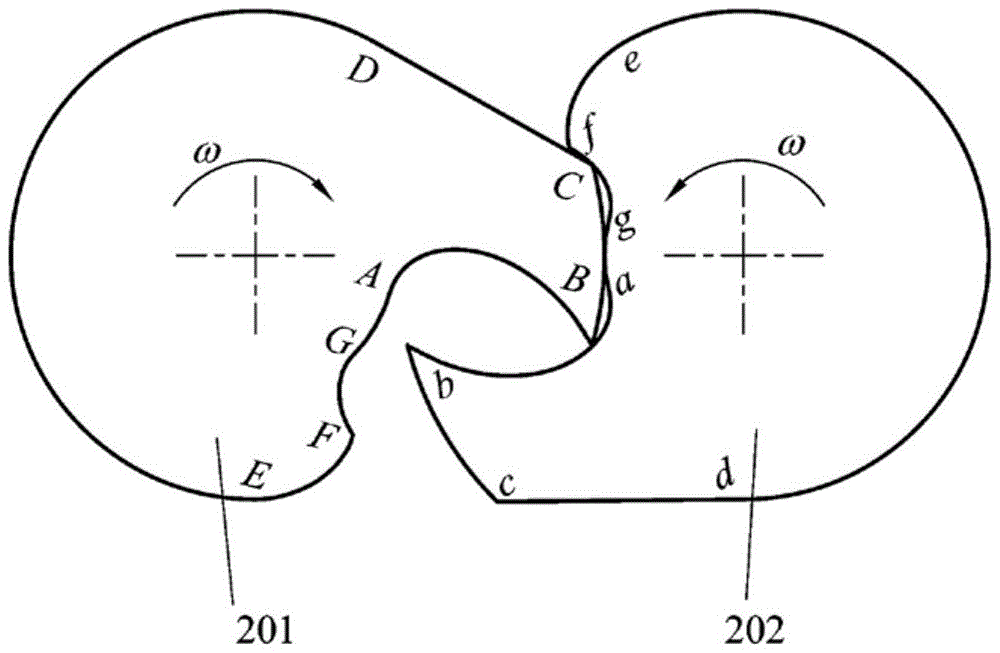
[0045] As shown in Figure 2, it is the working engagement diagram of two existing straight claw rotors; the two claw rotors have the same profile, and their relative rotations are staggered by a certain angle. When working, the two claw rotors are synchronized in different directions. Double swivel movement. (a) The cycloid AB and cycloid FG of the left claw rotor (201) in the figure mesh with the...


PUM


Abstract

The invention discloses a fully-meshed claw type rotor profile which comprises five arcs, two normal-direction equidistant curves of cycloid, a line segment and an envelope line of the line segment and sequentially comprises the pitch circle arc FG, the envelope line GH of the line segment, the normal-direction equidistant curve HI of cycloid, the claw bottom arc IA, the normal-direction equidistant curve AB of cycloid, the arc BC, the claw top arc CD, the arc DE and the line segment EF in the anticlockwise direction from a pitch circle. Except for the joint H of the envelope line GH of the line segment and the normal-direction equidistant curve HI of cycloid, smooth connection is achieved between every two of other profile bodies. Two meshed claw type rotors are completely the same, the curves can be meshed in work, all the profile bodies of the claw type rotors can be completely and correctly meshed, the strength and meshing sealing performance of the claw type rotors can be effectively improved, and the fully-meshed claw type rotor profile can be suitable for occasions with higher rotating speed, higher pressure and higher temperature.

Description

technical field [0001] The invention relates to a fully meshing claw rotor profile. Background technique [0002] The profile of the claw rotor has a very important influence on the performance of the claw fluid machinery, so the research on its profile construction is very important. The claw rotor is composed of two rotors with the same shape and capable of conjugate meshing. Through the synchronous counter-rotating double-rotation motion of the two claw rotors, the mutual meshing of the two claw rotor profiles is realized to provide periodicity. The variable volume of the working chamber realizes the suction, compression and discharge of gas. [0003] The meshing characteristics of the rotor profile directly determine the working performance of the claw rotor. The existing straight claw claw rotor profile includes: 3 sections of arc, 1 section of line, 2 sections of cycloid, and 1 section of envelope; However, the existing straight-claw-claw rotor profile has the follow...

Claims


Application Information

Patent Timeline
Patent Type & Authority Patents(China)
IPC IPC(8): F04C29/00F04C18/14
Inventor 王君姜希彤庞晓峰王增丽李强刘宏杰崔冬崔峰刘强
Owner CHINA UNIV OF PETROLEUM (EAST CHINA)
Why Eureka
Try Eureka