
Claw-type rotor profile

A claw-type and rotor technology, which is applied in the direction of rotary piston pumps, rotary piston machines, rotary piston/swing piston pump components, etc., can solve the problem of reducing the service life of claw rotors, poor sealing effect, and medium leakage Large and other problems, to achieve the effect of improving service life, improving volumetric efficiency, and enhancing sealing performance

Inactive Publication Date: 2014-08-13
CHINA UNIV OF PETROLEUM (EAST CHINA)
View PDF5 Cites 0 Cited by
  • Summary
  • Abstract
  • Description
  • Claims
  • Application Information

AI Technical Summary

Problems solved by technology

The meshing characteristics of the two claw rotor profiles play a crucial role in its working performance during work, but the existing claw rotor profiles have the following disadvantages: at the top of the claw, the arc at the top of the claw and the pendulum The line is not smoothly connected, and there are two sharp points at the connection point, so that when the claw rotor profile is engaged in work, these two sharp points mesh with the cycloid, and as a result, stress is easily generated at the sharp points Concentration and deformation, and relying on the engagement between points and curves to achieve sealing effect is also poor, the leakage of the medium at the sharp point engagement is large, and in addition, it is easy to wear at the sharp point, which ultimately reduces the service life of the claw rotor

Method used


Image

  • Claw-type rotor profile
  • Claw-type rotor profile
  • Claw-type rotor profile

Examples


Embodiment Construction

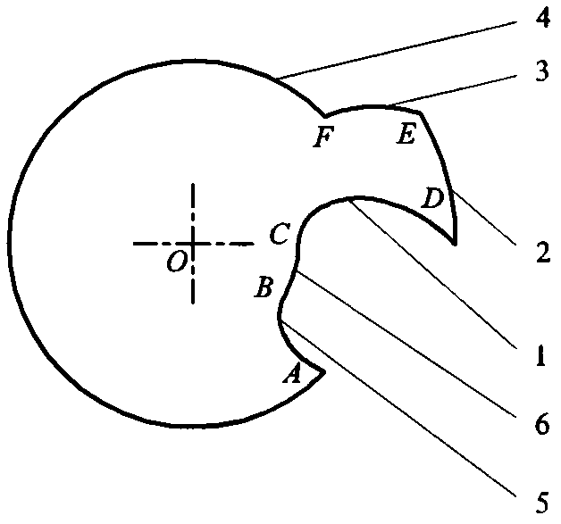
[0019] As shown in Figure 1, the original claw rotor profile is composed of three sections of arcs and three sections of cycloids, starting from the pitch circle in the counterclockwise direction: pitch circle arc FA, cycloid AB, claw bottom circle Arc BC, cycloid CD, claw top arc DE, and cycloid EF; the two connection points D and E of claw top arc DE are rough points, namely sharp points.

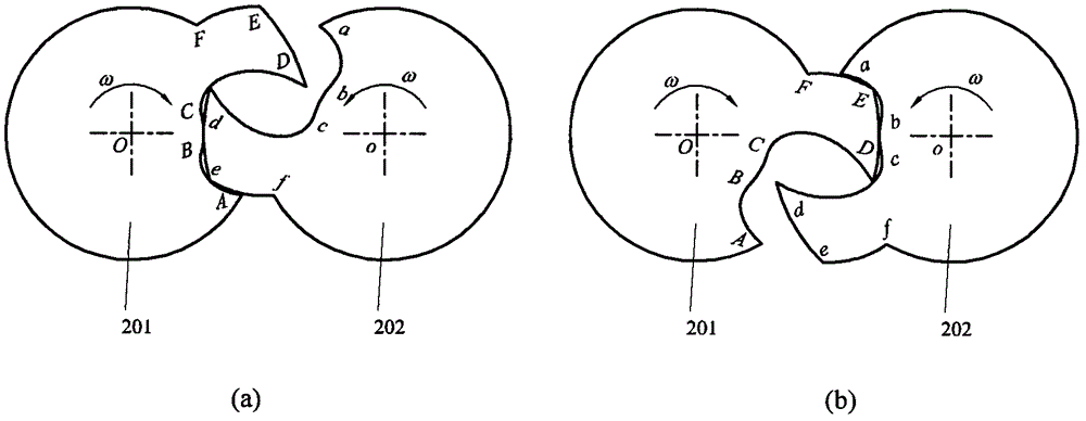
[0020] Such as figure 2 As shown, it is the working engagement diagram of the original two claw rotors; the two claw rotors have the same profile, and the relative rotation is staggered by a fixed angle. . (a) The cycloids AB and CD of the left rotor in the figure mesh with the points e and d of the right rotor respectively; (b) the points E and D of the left rotor in the figure respectively mesh with the points of the right rotor The cycloid ab and the cycloid cd mesh; it can be seen that the original claw rotor profile meshes with the curve during work.

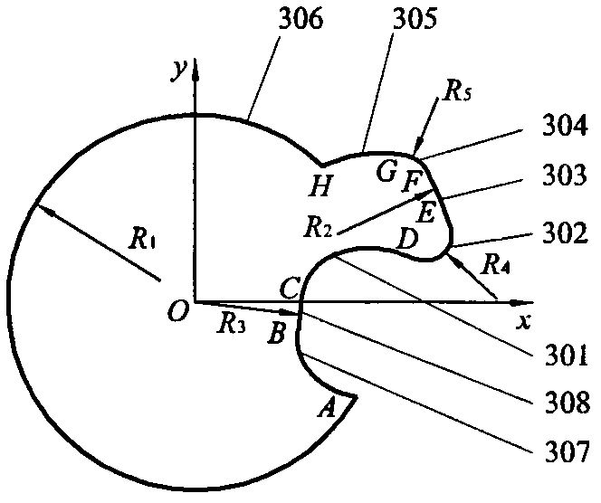
[0021] Such as image 3 As...


PUM


Abstract

A claw-type rotor profile comprises normal equidistant curves composed of five sections of arcs and three sections of cycloids. The smooth connection between a tooth crest arc and other profile lines can be realized by the rotor profile without sharp point connection at the tooth crest and the meshing between curves in operation can be realized, thus the claw-type rotor has higher strength and improved service life and is suitable for the occasions with faster speed, larger pressure and higher temperature, the application scope of claw-type compressors and claw-type vacuum pumps can be enlarged; meanwhile, the clearance volume formed by the claw-type rotor in the working mesh process is smaller, thus the volume efficiency can be improved; the claw-type rotor can reduce vibration and noise in the working process, thus the comprehensive performance is higher; the claw-type profiles can be evenly arrayed on the circumference of a pitch circle so as to obtain a dual-claw claw-type rotor profile and a three-claw claw-type rotor profile, thus the claw-type rotor profile provided by the invention is crucial to enrich the types of the claw-type rotor profile and promote the development of claw-type compressors and claw-type vacuum pumps.

Description

technical field [0001] The invention relates to a profiled line of a claw rotor. Background technique [0002] The claw rotor is the key component of the claw compressor or claw vacuum pump. It contains two claw rotors with the same shape and capable of conjugate meshing. , to achieve the mutual meshing of the two claw rotor profiles to provide a periodically changing working chamber volume to achieve gas suction, compression and discharge. The meshing characteristics of the two claw rotor profiles play a crucial role in its working performance during work, but the existing claw rotor profiles have the following disadvantages: at the top of the claw, the arc at the top of the claw and the pendulum The line is not smoothly connected, and there are two sharp points at the connection point, so that when the claw rotor profile is engaged in work, these two sharp points mesh with the cycloid, and as a result, stress is easily generated at the sharp points Concentration and defo...

Claims


Application Information

Patent Timeline
Patent Type & Authority Patents(China)
IPC IPC(8): F04C29/00F04C18/14
Inventor 王君刘凯光刘凯章大海徐树根曲燕李雪琴
Owner CHINA UNIV OF PETROLEUM (EAST CHINA)
Learn More