
Fixing device

A technology of a rotating body and a rotating direction, which is applied to instruments, equipment of electrical recording technology applying charge patterns, optics, etc., can solve the problems of temperature drop of the fixing belt 506 and other problems, and achieve the effect of reducing heat loss

Active Publication Date: 2015-09-23
KONICA MINOLTA INC
View PDF4 Cites 0 Cited by
  • Summary
  • Abstract
  • Description
  • Claims
  • Application Information

AI Technical Summary

Problems solved by technology

Therefore, the temperature of the fixing belt 506 drops during the period from passing through the heating roller 504 to reaching the nip, and heat loss occurs.

Method used


Image

  • Fixing device
  • Fixing device
  • Fixing device

Examples


other Embodiment approach

[0111] The fixing device of the present invention is not limited to the above-mentioned fixing devices 20 , 20 a , and 20 b , and changes can be made within the scope of the gist thereof.

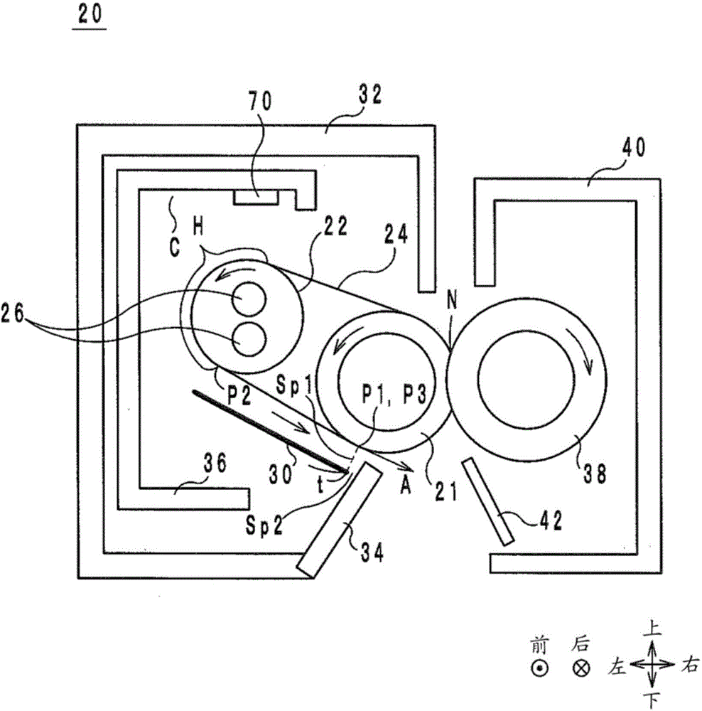
[0112] Also, the reflection plate 30 and the rib 34 may be in contact, but preferably, their contact area is as small as possible. Thereby, heat conduction between the reflection plate 30 and the rib 34 can be suppressed.

[0113] In addition, the rib 34 may be integrated with the outer cover 32 . Thereby, a reduction in the number of parts is achieved.

[0114] In addition, the fixing roller 21 may be positioned obliquely above the heating roller 22 .


PUM


Abstract

A fixing device having: a first rotating member rotating in a first rotational direction; a second rotating member contacting the first rotating member and thereby forming a nip through which a printing medium passes, wherein the second rotating member rotates in a second rotational direction opposite to the first rotational direction; a heating unit heating the first rotating member in a heating section not overlapping with the nip when viewed in a plan view in the predetermined direction; and a first reflective member facing at least a part of a portion of the first rotating member that is located on a downstream side in the first rotational direction relative to the heating section but on an upstream side in the first rotational direction relative to the nip, the first reflective member having a reflection surface on the side facing the first rotating member.

Description

technical field [0001] The present invention relates to a fixing device, and more particularly, to a fixing device for an image forming device. Background technique [0002] As an invention of a conventional fixing device, for example, a fixing device described in Patent Document 1 is known. Figure 5 It is a configuration diagram of a fixing device 500 described in Patent Document 1. FIG. [0003] The fixing device 500 includes a fixing roller 502 , a heating roller 504 , a fixing belt 506 , a halogen heater 508 , a reflection member 510 , and a pressure roller 512 . The fixing belt 506 is stretched between the fixing roller 502 and the pressure roller 504 . The halogen heater 508 is provided inside the heating roller 504 and heats the fixing belt 506 via the heating roller 504 . The reflection member 510 faces a portion of the fixing belt 506 in contact with the heating roller 504 and reflects heat radiated from the fixing belt 506 . The pressure roller 512 is in pressu...

Claims


Application Information

Patent Timeline
Patent Type & Authority Applications(China)
IPC IPC(8): G03G15/20
CPCG03G15/2053G03G15/2046
Inventor 早瀬徹深谷守片冈尚树田丸刚士
Owner KONICA MINOLTA INC
Features
  • Generate Ideas
  • Intellectual Property
  • Life Sciences
  • Materials
  • Tech Scout
  • Unparalleled Data Quality
  • Higher Quality Content
  • 60% Fewer Hallucinations
Learn More