Power reception coil unit

a power reception coil and power technology, applied in the direction of transformers/inductances, magnetic cores of transformers/inductances, inductances, etc., can solve the problems of eddy current flowing and the decrease of power transmission efficiency, and achieve the effect of efficient suppression of eddy curren

Inactive Publication Date: 2010-12-23
PANASONIC CORP
View PDF11 Cites 62 Cited by
  • Summary
  • Abstract
  • Description
  • Claims
  • Application Information

AI Technical Summary

Benefits of technology

[0005]In view of the above insufficiency, the present invention has been aimed to propose a power reception coil unit capable of suppressing a temperature rise of the magnetic plate as well as improving power transmission efficiency.
[0007]According to the invention, the gap formed in the magnetic plate delimits the eddy current flowing through the magnetic plate. Thus, it is possible to suppress the temperature rise caused by the eddy current flowing through the magnetic plate, thereby reducing a heat loss. Also, the reduction of the eddy-current can improve power transmission efficiency.
[0009]According to the preferred embodiment, the gap breaks the eddy current because the slit penetrates through the magnetic plate. Therefore, the magnetic plate can more reduce the eddy current than in a case where the gap is provided in the form of a groove.
[0011]According to the preferred embodiment, the magnetic plate can be easier to handle than in a case where the gap is provided in the form of a slit.
[0013]According to the preferred embodiment, it is possible to efficiently suppress the eddy current, yet restraining the gap from blocking the flow of the magnetic flux.
[0015]According to the preferred embodiment, it is possible to efficiently suppress the eddy current.

Problems solved by technology

However, because of the magnetic plate having electrical conductivity, a magnetic field generated by the power supply coil is likely to cause eddy current which flows through the magnetic plate.
Further, an eddy-current loss causes a decrease in the power transmission efficiency.

Method used


Image

  • Power reception coil unit
  • Power reception coil unit
  • Power reception coil unit

Examples


first embodiment

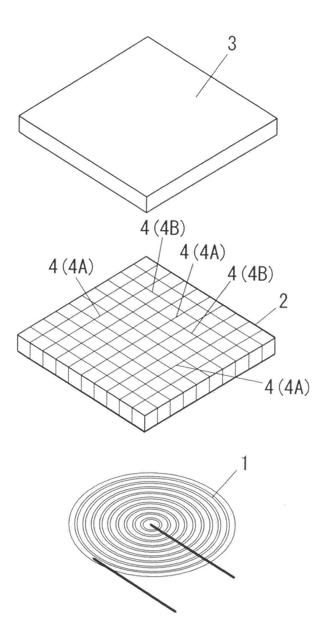
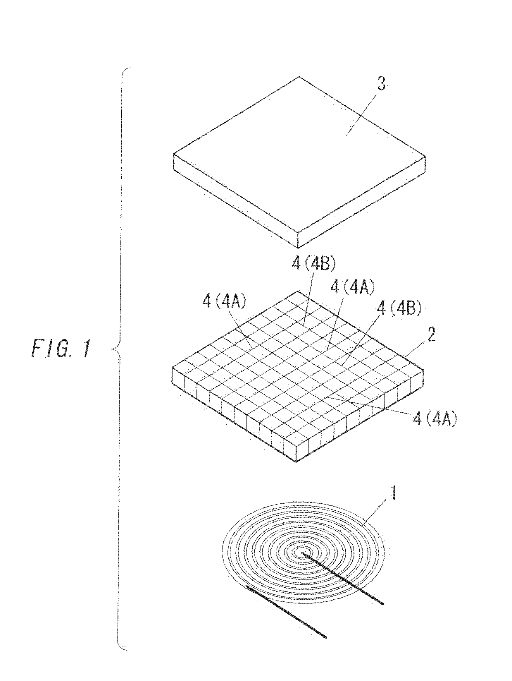
[0039]A power reception coil unit of the present embodiment constitutes a contactless power transmission apparatus configured to transmit an electric power in a noncontact manner by use of electromagnetic induction together with a power supply coil unit (not shown) having a power supply coil. In the contactless power transmission apparatus, generally, the power reception coil is separated from the power supply coil unit. The power reception coil unit is positioned at a prescribed position for the power supply coil unit in order to transmit an electrical power. The prescribed position is defined to be a position where a transformer has its power supply coil and power reception coil magnetically coupled to each other to render the power supply coil as a primary coil and the power reception coil as a secondary coil. The contactless power transmission apparatus is configured to utilize the transformer to transmit an electrical power to the power reception coil unit from the power supply...

second embodiment

[0055]As shown in FIGS. 5A and 5B, the power reception coil unit of the present embodiment is different in a configuration of the magnetic plate 2 from that of the first embodiment. With regard to other components, the power reception coil unit of the present embodiment is the same as that of the first embodiment, and no explanation is deemed necessary.

[0056]The magnetic plate 2 in accordance with the present embodiment is made of a magnetic material having electrical conductivity and is shaped into a rectangular (square, in the illustrative instance) flat plate shape in a similar fashion as the first embodiment. However, the magnetic plate 2 is provided in the surface (lower surface, in FIG. 5A) with a plurality of linear grooves 7 instead of the slits 4. In the present embodiment, each of the grooves 7 defines the gap formed in the surface of the magnetic plate 2.

[0057]The plurality of grooves 7 is formed in the magnetic plate 2 in a reticular pattern. In more detail, the magnetic...

third embodiment

[0063]As shown in FIG. 7, the power reception coil unit of the present embodiment is different in the configuration of the magnetic plate 2 from that of the first embodiment. With regard to other components, the power reception coil unit of the present embodiment is the same as that of the first embodiment, and no explanation is deemed necessary.

[0064]The magnetic plate 2 in accordance with the present embodiment is provided on a center of the surface with a circular cylindrical protrusion 2a extending through a center of the power reception coil 1. Further, the magnetic plate 2 is provided on the periphery of the surface with a peripheral wall 2b which surrounds the power reception coil 1. The peripheral wall 2b has its inner periphery shaped into a circular shape. The peripheral wall 2b has its center aligned with the center of the protrusion 2a.

[0065]In the magnetic plate 2 of the present embodiment, the power reception coil 1 is placed in an annular space 2c between the protrus...


PUM

PropertyMeasurementUnit
electric poweraaaaaaaaaa
electrical conductivityaaaaaaaaaa
magnetic fluxaaaaaaaaaa

Abstract

A power reception coil unit includes a power reception coil configured to be magnetically coupled to a power supply coil during a power transmission and a magnetic plate made of a magnetic material having electrical conductivity. The power reception coil is a planar coil. The magnetic plate has its surface opposed to the power reception coil and is parallel to the power reception coil. The magnetic plate is provided with a plurality of slits in the surface.

Description

TECHNICAL FIELD[0001]The present invention is directed to power reception coil units, more particular, to a power reception coil unit for a contactless power transmission apparatus configured to transmit an electric power in a noncontact manner by use of electromagnetic induction.BACKGROUND ART[0002]In the past, as disclosed in Japanese laid-open patent publication No. 2006-311712, there is known a contactless power transmission apparatus configured to transmit an electric power in a noncontact manner by use of electromagnetic induction. This kind of the contactless power transmission apparatus includes a power supply coil unit having a power supply coil and a power reception coil unit having a power reception coil configured to be magnetically coupled to the power supply coil.[0003]The aforementioned Japanese laid-open patent publication discloses a planar coil is adopted as the power reception coil. In comparison with a coil wound around a core or bobbin, the planar coil has a mer...

Claims


Application Information

Patent Timeline
Patent Type & Authority Applications(United States)
IPC IPC(8): H02J17/00H01F38/14
CPCH01F27/24H01F27/34H02J5/005H01F2027/348H01F38/14H02J50/70H02J50/10H02J50/90
Inventor KITAMURA, KOTASUZUKI, MASAYUKIYABUUCHI, HIDEKAZU
Owner PANASONIC CORP
Why Eureka
Try Eureka