Power generation system

a power generation system and power generation technology, applied in steam engine plants, machines/engines, mechanical equipment, etc., can solve the problems of unfavorable economic development, unfavorable economic development, and inability to develop alternative energy sources on a large scale, so as to achieve efficient and practicable manner

Inactive Publication Date: 2006-11-30
JEROME ALLAN
View PDF0 Cites 59 Cited by
  • Summary
  • Abstract
  • Description
  • Claims
  • Application Information

AI Technical Summary

Benefits of technology

[0013] It is an object of the present disclosure to provide a power generation system wher...

Problems solved by technology

While such sources as wind, solar, tidal and nuclear energies are often presented as potential means for meeting society's energy needs, the implementation and commercialization of such technologies has been slow.
Alternative energy sources have failed to yet develop on a large scale due largely to the fact that they are economically unviable, or for various safety and other reasons.
Not only is the generator system relatively complex and unwieldy, such systems tend to be quite large and are typically suitable only for large-scale power generation facilities or vehicles.
Accordingly, Cox suffers from many of the same problems associated with conventional power generation systems, namely, scarcity of resources required to operate the device and potentially undesirable emissions.
While Edelson presents a design showing promise in certain narrow applications, the concepts disclosed therein are not capable of meeting the multiplicity of demands required of large scale, efficient and commercially viable power generation technologies.
In other words, while certain known systems present important steps toward achieving society's energy goals, most if not all still fall short of the mark.
While...

Method used


Image

  • Power generation system
  • Power generation system
  • Power generation system

Examples


Embodiment Construction

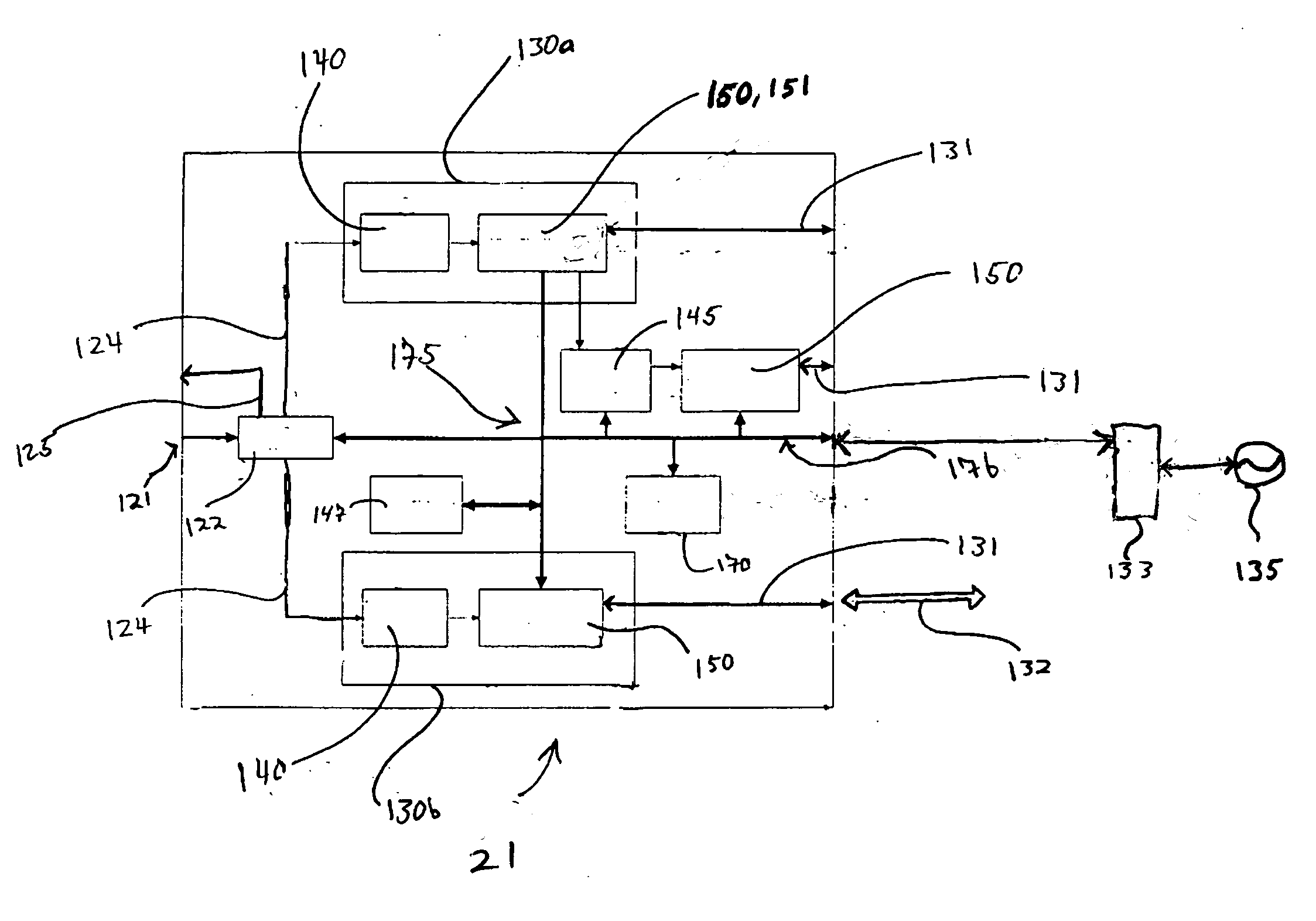
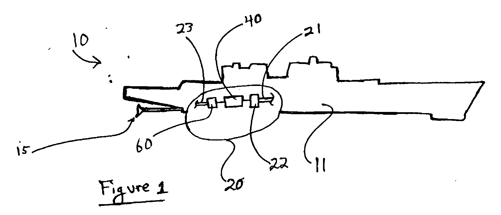
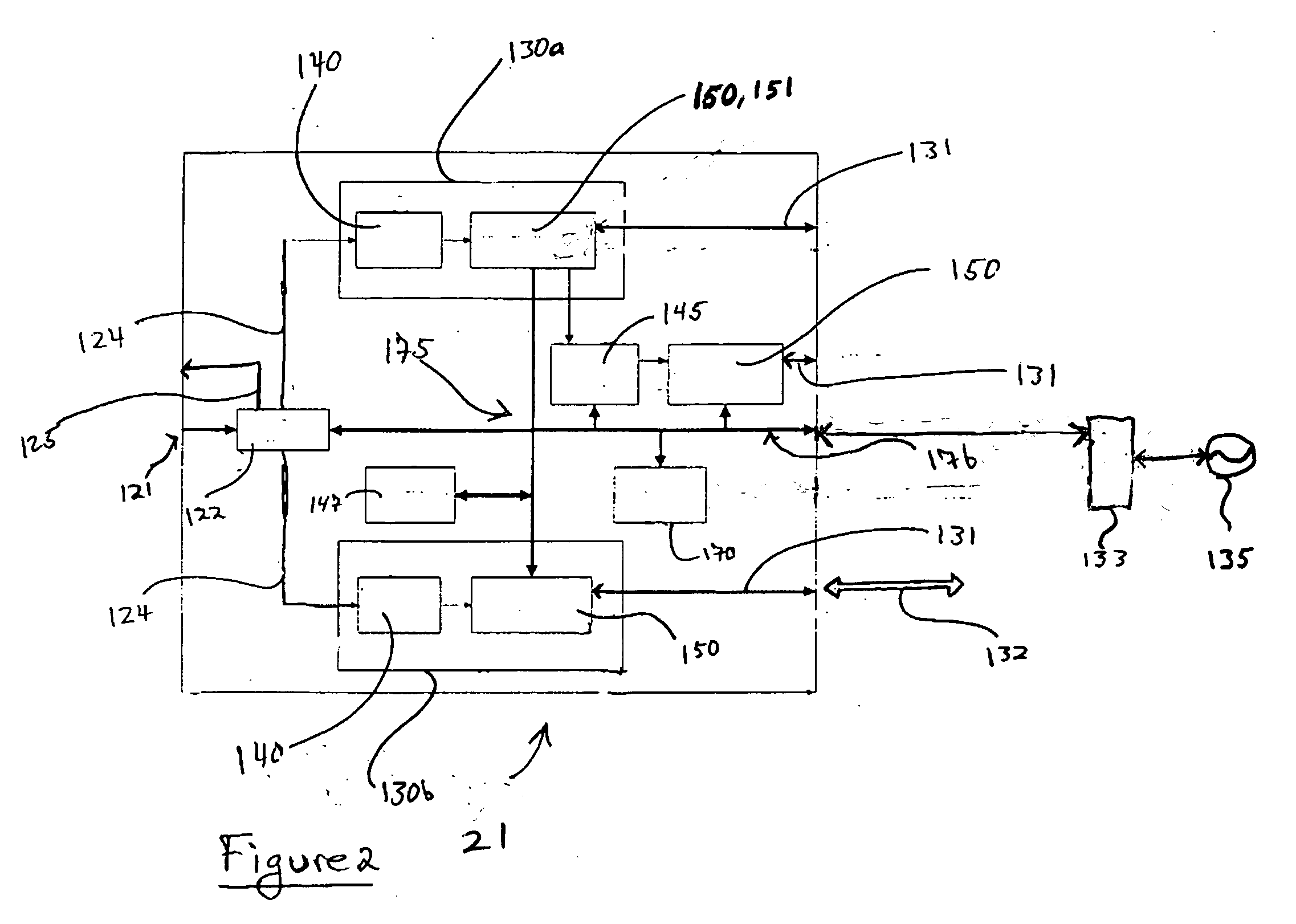
[0046] Referring to FIG. 1, there is shown a vehicle 10 having a propulsion system 20 housed within a vehicle body 11, according to the present disclosure. Propulsion system 20 may include a “hydrogen plasma engine”, described below. Vehicle 10 is shown in the context of a marine vessel having a propeller 15, such as a shaft-driven or podded propeller; however, it should be appreciated that the present disclosure is not thereby limited, and is equally applicable to virtually all-mobile vehicles requiring a propulsion system. In further embodiments, applications of the power generation and storage components of system 20, e.g. part or all of the “hydrogen plasma engine” described below, are illustrated in the context of machines other than mobile vehicles. Thus, it will be appreciated that the embodiments of the present disclosure will have a very wide range of application in environments where power generation is necessary.

[0047] In certain contemplated embodiments propulsion syste...


PUM


Abstract

A thermal plasma generator may be used in conjunction with at least one thermal to electric converter, such as a solid state thermal to electric energy to electric converter. A micropipe heat pump extracts heat from the at least one thermal to electric energy device, which in turn may convert the heat into electrical power. The power generation system may be disposed within a vehicle, and provide electrical power for propelling the vehicle.

Description

[0001] This application claims the benefit of the filing date of U.S. Provisional Patent Application No. 60 / 613,921, Filed Sep. 28, 2004.TECHNICAL FIELD [0002] The present disclosure relates generally to power generation systems and thermal management in power generation systems, and relates more particularly to a thermal and electrical power generation core component incorporating a hydrogen plasma engine, suitable for use in a wide range of applications. The present disclosure still further relates to a unique heat pump for use in a hydrogen plasma engine power generation system, and for thermal management in various other devices and processes. BACKGROUND [0003] Power generation and availability are integral to the functioning of modern society, touching virtually every aspect of daily life. With the continuing depletion of fossil fuel resources, and the increased economic and environmental costs of their use, recent decades have seen an intensification of the search for viable a...

Claims


Application Information

Patent Timeline
IPC IPC(8): F01K25/08
CPCF01K15/04Y02B30/52Y02T10/166F02G5/00Y02T10/12
Inventor JEROME, ALLAN
Owner JEROME ALLAN
Why Eureka
Try Eureka