Motor vehicle door lock

A motor vehicle door lock, electric technology, applied in electric car locks, electric locks, vehicle locks and other directions, can solve problems such as complex mechanical technical solutions

Active Publication Date: 2017-04-05
KIEKERT AG
View PDF5 Cites 0 Cited by
  • Summary
  • Abstract
  • Description
  • Claims
  • Application Information

AI Technical Summary

Problems solved by technology

Although this has proven to be advantageous in principle, mechanically complex technical solutions often result here

Method used


Image

  • Motor vehicle door lock
  • Motor vehicle door lock
  • Motor vehicle door lock

Examples


Embodiment Construction

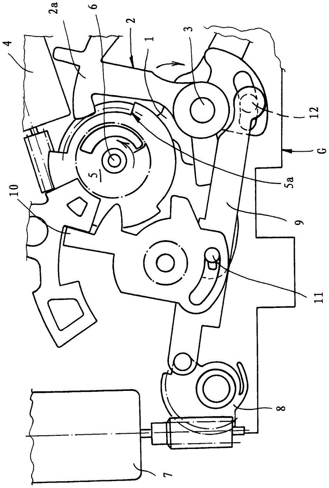
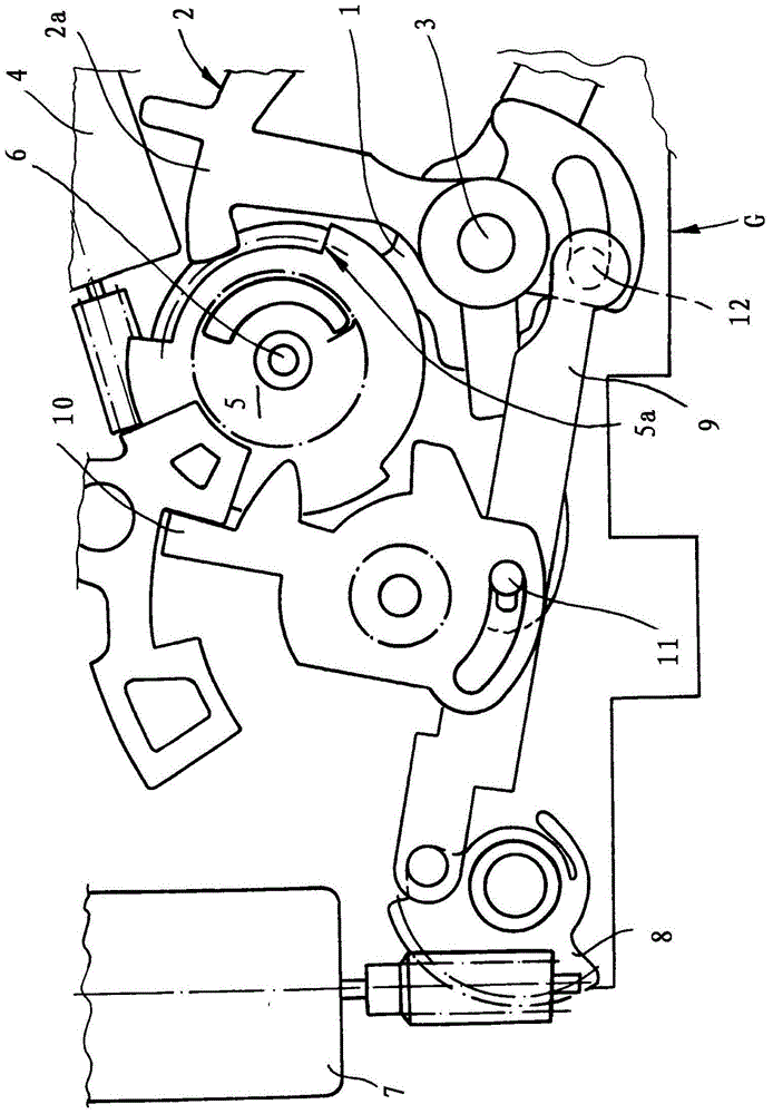
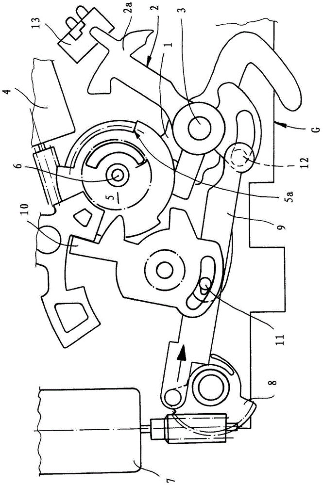
[0012] The motor vehicle door locks shown in the figures are as usual equipped with a locking mechanism, not shown in detail, which essentially comprises a rotary locking fork and a locking pawl. The locking mechanism is acted on by a trigger lever 1 , which is mounted in housing G together with the locking element or locking lever 2 about a common axis 3 . A clockwise rotational movement of the trigger lever 1 about its axis 3 causes the locking mechanism to be opened. To this end, the trigger lever 1 acts on the pawl of the locking mechanism in such a way that the pawl is removed from the associated rotary catch and the rotary catch is opened with the aid of a spring.

[0013] In order to start the described and in figure 1 For the clockwise movement of the trigger lever 1 shown in , an electric drive 4, 5 is provided. Electric driving device 4,5 is mainly made up of motor 4 and transmission wheel 5.

[0014] The electric motor 4 is equipped on the output side with a worm...


PUM


Abstract

The invention relates to a motor vehicle door lock, which is equipped with a locking mechanism and an electric drive (4, 5) for electrically opening the locking mechanism. According to the invention, an additional drive (7, 8) is provided in addition to the electric drive (4, 5) for electrically opening the locking mechanism. In order to open the locking mechanism electrically by means of the electric drive (4, 5), the additional drive (7, 8) releases the mechanical security of the electric drive (4, 5) via the locking element (2).

Description

technical field [0001] The invention relates to a motor vehicle door lock comprising a locking mechanism and an electric drive device for electrically opening the locking mechanism. Background technique [0002] A motor vehicle door lock of the aforementioned construction is described, for example, in the applicant's patent application WO 02 / 31298 A1. In this case, not only can the locking mechanism be opened electrically, but at the same time a mechanical connection is provided between the actuating lever and the locking mechanism for emergency opening of the locking mechanism. This is also referred to here as the so-called Temporary Crash Redundancy (TCR). That is to say, it is ensured that the locking mechanism can be opened by the actuating lever even in so-called emergency operation / failure states or in the case of emergency opening, for example in the event of a crash. [0003] The electrical opening of the locking mechanism by means of an electric drive usually take...

Claims


Application Information

Patent Timeline
Patent Type & Authority Patents(China)
IPC IPC(8): E05B81/14E05B81/06E05B77/02E05B77/26E05B77/28E05B81/90E05B77/12
CPCE05B81/14E05B77/02E05B77/26E05B77/28E05B81/06E05B79/10E05B85/243
Inventor C·巴尔默沙伊特
Owner KIEKERT AG
Why Eureka
Try Eureka