Automobile clutch master cylinder

A clutch master cylinder, automobile technology, applied in clutches, fluid-driven clutches, non-mechanical-driven clutches, etc., can solve the problems of reducing driving comfort, difficulty in the return of the push rod, difficulty in the return of the pedal arm, etc., to eliminate discomfort, eliminate Negative pressure, the effect of reducing the return resistance

Inactive Publication Date: 2015-10-07
CHERY AUTOMOBILE CO LTD
View PDF12 Cites 5 Cited by
  • Summary
  • Abstract
  • Description
  • Claims
  • Application Information

AI Technical Summary

Problems solved by technology

When the clutch pedal is stepped on, the push rod pushes the piston to move, so that the oil in the cylinder is compressed from the oil outlet to the working oil cylinder on the clutch, and the clutch hydraulic oil obtained by the working oil cylinder makes the clutch work, thereby realizing the clutch. During the return process of the pedal, the push rod returns, drags the return of the piston, and the return of the hydraulic oil, thereby realizing the return of the pedal arm. Since the moving speed of the piston is greater than the return speed of the hydraulic oil during the return process, the clutch master There is a certain vacuum in the cylinder chamber on the side where the cylinder oil outlet is located, so it is difficult to return the push rod, which makes it difficult to return the pedal arm and reduces the driving comfort

Method used


Image

  • Automobile clutch master cylinder
  • Automobile clutch master cylinder
  • Automobile clutch master cylinder

Examples


Embodiment Construction

[0015] combined with Figures 1 to 11 , the present invention is described in further detail:

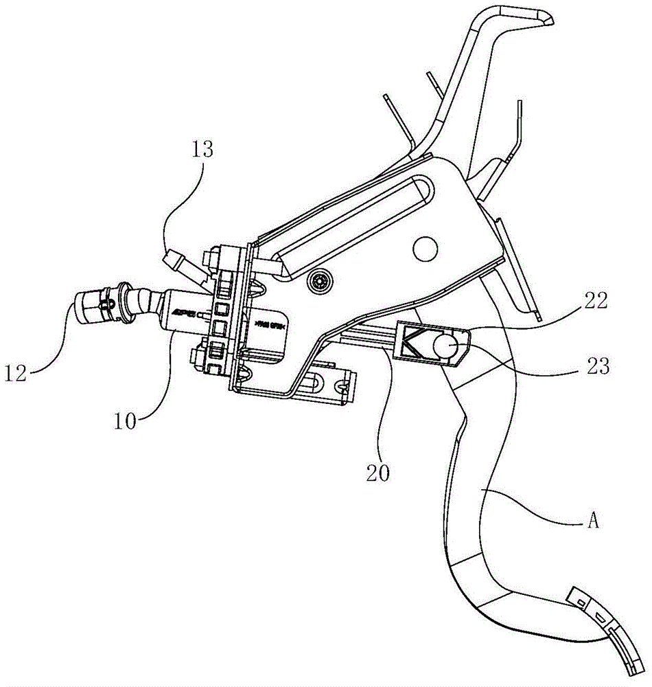
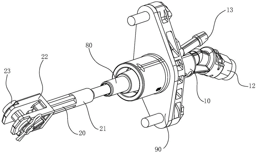
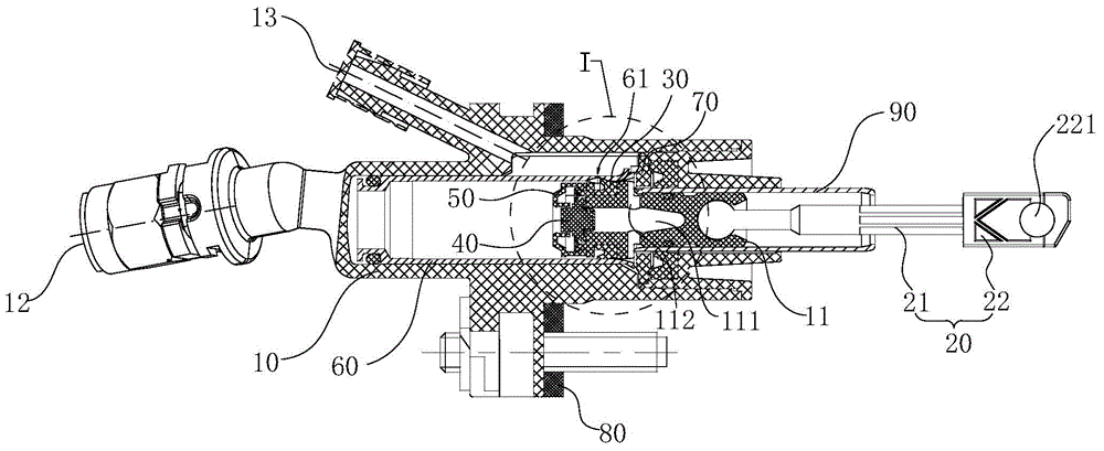
[0016] An automobile clutch master cylinder, comprising a cylinder body 10 and a piston 11 arranged in the cylinder body 10, a sealing ring 30 is arranged on the piston 11, and the sealing ring 30 divides the inner cavity of the cylinder body 10 into two chambers before and after, and the piston 11 The front end of the push rod 20 is connected to one end of the push rod 20, and the other end of the push rod 20 extends away from the cylinder block axially and is hingedly connected with the clutch pedal arm A. The rear end of the rear chamber of the cylinder block 10 is connected to the oil outlet pipe 12, The oil inlet pipe 13 is connected to the front chamber of the cylinder body 10 from the through hole provided on the pipe wall of the cylinder body 10, and the piston 11 is provided with a passage 111 connecting the front and rear chambers of the cylinder body 10, and a check valve...


PUM


Abstract

The invention relates to an automobile clutch master cylinder which comprises a cylinder body and a piston arranged in the cylinder body. A sealing ring is arranged on the piston and divides an inner cavity of the cylinder body into a front chamber and a rear chamber. The front end of the piston is connected with one end of a push rod. The other end of the push rod extends away from the cylinder body in the axial direction of the cylinder body and is hinged to a clutch pedal arm. The rear end of the rear chamber of the cylinder body is provided with an oil outlet pipe. An oil inlet pipe is communicated into the front chamber of the cylinder body from a through hole formed in the pipe wall of the cylinder body. A path for communicating the front chamber with the rear chamber is formed in the piston. A one-way valve is arranged on the path. In the communicating direction of the one-way valve, oil is supplied from the front chamber to the rear chamber of the cylinder body. When negative pressure exists in the rear chamber of the cylinder body, oil in the front chamber passes through the path and the one-way valve to enter the rear chamber, so that the negative pressure in the rear chamber is eliminated, the return stroke resistance of a pedal is reduced, and driving discomfortableness of a driver is eliminated.

Description

technical field [0001] The invention belongs to the field of automobile clutches, in particular to an automobile clutch master cylinder. Background technique [0002] The automobile clutch master cylinder is used as the clutch control mechanism of the automobile to realize the connection between the clutch pedal and the clutch. The automobile clutch master cylinder mainly includes a cylinder body, a piston is arranged in the cylinder body, and a push rod is arranged at one end of the piston, and the push rod extends out of the cylinder body Hinged with clutch pedal arm. When the clutch pedal is stepped on, the push rod pushes the piston to move, so that the oil in the cylinder is compressed from the oil outlet to the working oil cylinder on the clutch, and the clutch hydraulic oil obtained by the working oil cylinder makes the clutch work, thereby realizing the clutch. During the return process of the pedal, the push rod returns, drags the piston back, and the hydraulic oil...

Claims


Application Information

Patent Timeline
Patent Type & Authority Applications(China)
IPC IPC(8): F16D25/12
Inventor 蔡以涛
Owner CHERY AUTOMOBILE CO LTD
Why Eureka
Try Eureka