Ship propeller

A technology for propellers and ships, applied in the direction of ship propulsion, propulsion components, ship components, etc., can solve the problems of limiting ship speed, thrust dispersion, unfavorable reaction force, etc., to reduce energy and power loss, consistent thrust direction, and thrust direction scattered effect

Inactive Publication Date: 2012-10-03
徐洪林
View PDF6 Cites 8 Cited by
  • Summary
  • Abstract
  • Description
  • Claims
  • Application Information

AI Technical Summary

Problems solved by technology

Among them, propeller propulsion and water jet propulsion are the most common propulsion methods. The disadvantages of propeller propulsion are: first, the structure is complex and there are many mechanical transmission links, which not only has a high failure rate, but also reduces the propulsion efficiency; second, the thrust of the propeller device is scattered during operation. In addition, the frontal resistance of the propeller itself is relatively large, which limits the increase of the speed of the ship; the existing water jet propulsion has the advantages of high speed, low noise, environmental protection, energy saving and emission reduction. It is composed of a water pump, a water suction pipe, and a water spray pipe. Power, sucking water from the bottom hole of the ship, relying on the high-pressure water pump at the stern through the bottom pipe, ejecting high-pressure and high-speed water flow, and using the reaction force of the water flow to propel the ship's movement
The disadvantages of this water jet propulsion method are that the efficiency is low, the structure and process are complicated, the construction cost is high, the maintenance is difficult, and the high-pressure water pump is easily damaged.
In addition, the above two types are propelled along the water, which is not conducive to generating a large reaction force

Method used


Image

  • Ship propeller
  • Ship propeller
  • Ship propeller

Examples


Embodiment Construction

[0032] The principles and features of the present invention are described below in conjunction with the accompanying drawings, and the examples given are only used to explain the present invention, and are not intended to limit the scope of the present invention.

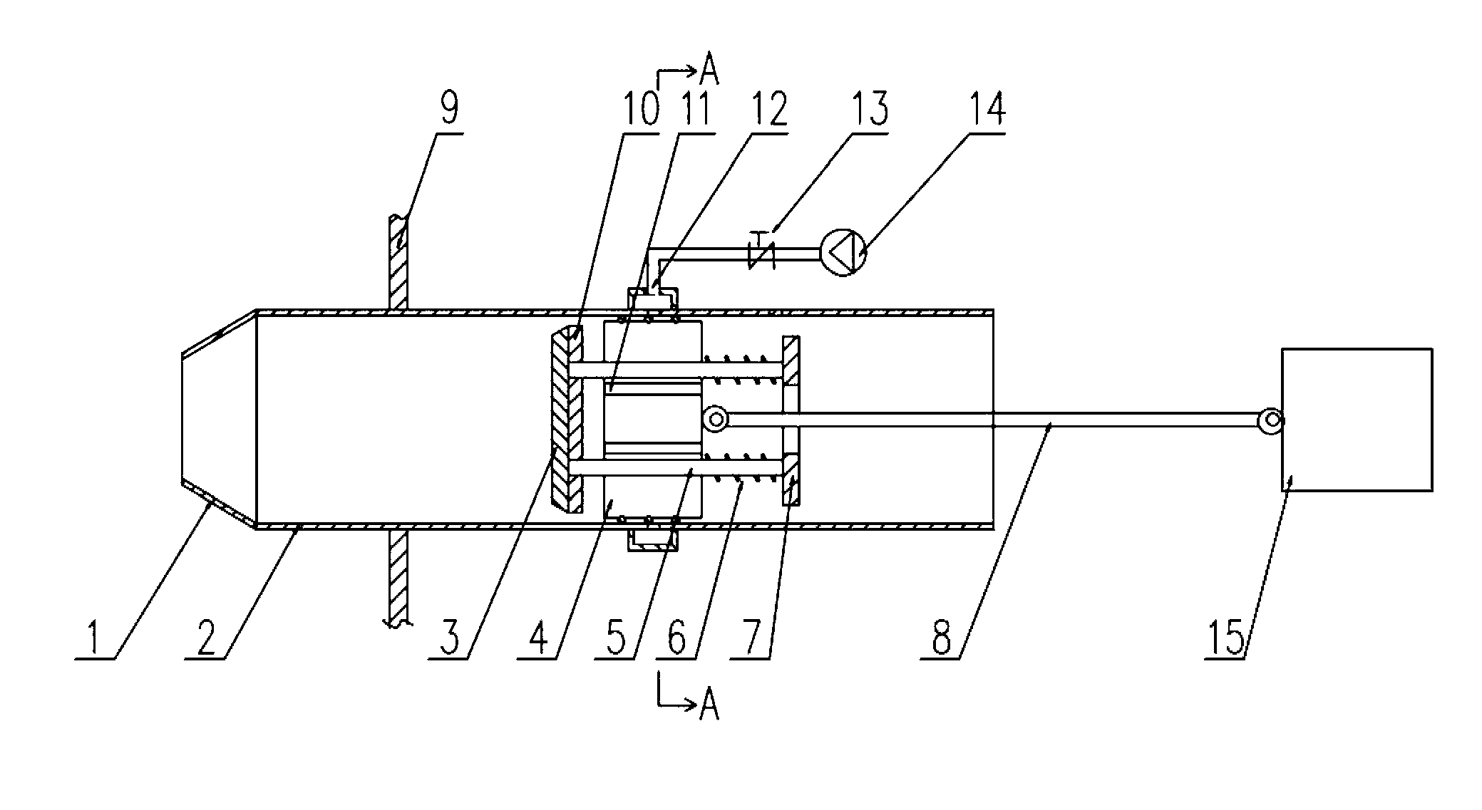
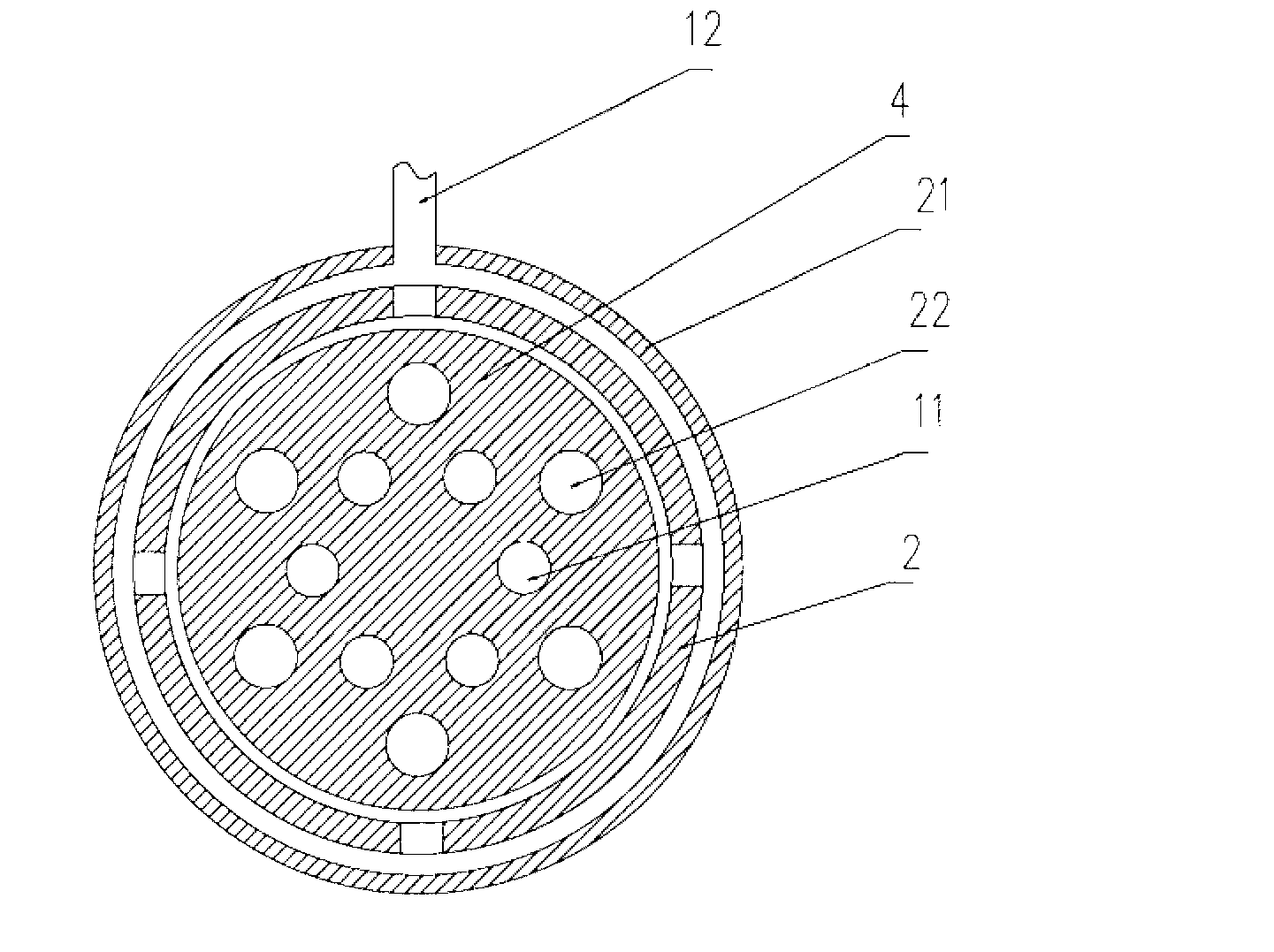
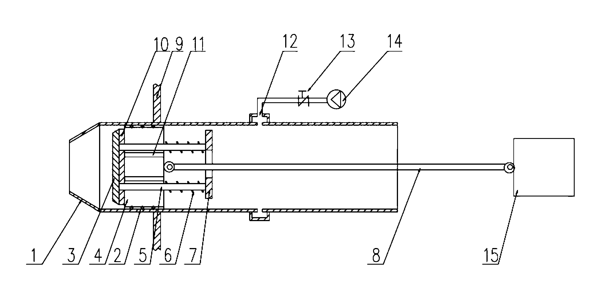
[0033] Such as Figure 1 to Figure 9 As shown, a ship propeller includes a propulsion mechanism and a drive mechanism. It is characterized in that the propulsion mechanism includes a cylinder liner 2, a piston 4, a piston connecting rod 8 and an automatic opening device for a pressure limiting valve, and the piston 4 is set on the In the cylinder liner 2 , one end of the piston connecting rod 8 is hingedly connected to the piston 4 , and the other end is connected to the driving mechanism. The piston 4 is provided with a valve stem hole 22 and a vent hole 11 . A sliding sleeve is also arranged in the valve stem hole 22 .

[0034] The automatic opening device for the pressure-limiting valve includes a valve 3, a val...


PUM


Abstract

The invention relates to a ship propeller, which comprises a pushing mechanism and a driving mechanism. The ship propeller is characterized in that the pushing mechanism comprises a cylinder sleeve, a piston, a piston connecting rod and a pressure-limiting automatic valve opening device, wherein the piston is sleeved in the cylinder sleeve, one end of the piston connecting rod is hinged with the piston, the other end of the piston connecting rod is connected with the driving mechanism, and the piston is provided with a valve rod hole and a ventilation hole; and the pressure-limiting automatic valve opening device comprises a valve, a valve rod, a spring and a spring bottom plate, wherein the valve is of a disk shape, the valve rod is inserted into the valve rod hole, one end of the valve rod is connected with the valve, the other end of the valve rod is connected with the spring bottom plate, and the spring is arranged between the piston and the spring bottom plate and is sleeved on the valve rod. The ship propeller has the beneficial effects that the ship propeller is simple in structure, low in manufacturing cost, reliable in work, high in propelling speed and low in noise, and is energy-saving and environment-friendly; and due to the simple structure, the loss in energy and power is reduced.

Description

technical field [0001] The invention relates to a ship power device, in particular to a ship propeller. Background technique [0002] The ship's propulsion device is a tool that provides thrust on the ship. Its function is to convert the power provided by the ship's power device into the main thrust and propel the ship forward. There are many forms of ship propulsion devices, such as gas turbine propulsion, propeller propulsion, electric propulsion, superconducting magnetic fluid propulsion, water jet propulsion, etc. Each propulsion method has its advantages and disadvantages. Among them, propeller propulsion and water jet propulsion are the most common propulsion methods. The disadvantages of propeller propulsion are: first, the structure is complex and there are many mechanical transmission links, which not only has a high failure rate, but also reduces the propulsion efficiency; second, the thrust of the propeller device is scattered during operation. In addition, the ...

Claims


Application Information

Patent Timeline
Patent Type & Authority Applications(China)
IPC IPC(8): B63H11/02
Inventor 徐洪林徐晓光
Owner 徐洪林
Why Eureka
Try Eureka