Inflatable obstruction device for the pyloric sphincter

A technology of expanding tubes and components, which is applied in the field of flow devices, and can solve problems such as long-term obstruction and pylorus obstruction

Active Publication Date: 2015-10-07
EASYNOTES
View PDF5 Cites 5 Cited by
  • Summary
  • Abstract
  • Description
  • Claims
  • Application Information

AI Technical Summary

Problems solved by technology

[0003] However, there are some chronically ill patients who require long-term pyloric obstruction
Chronic blocking is problematic

Method used


Image

  • Inflatable obstruction device for the pyloric sphincter
  • Inflatable obstruction device for the pyloric sphincter
  • Inflatable obstruction device for the pyloric sphincter

Examples


Embodiment Construction

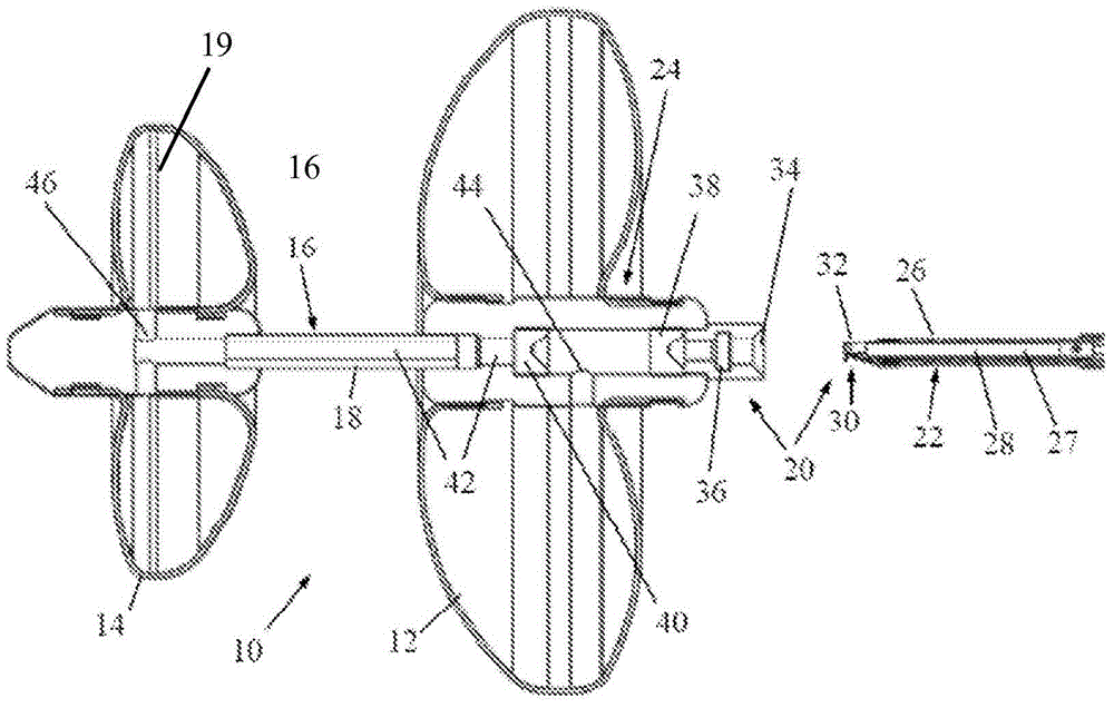
[0019] see now figure 1 , which illustrates an occlusion device (or plug) 10 and delivery system 20 constructed and operative in accordance with one embodiment of the present invention.

[0020] The occlusion device 10 includes a proximal occlusion balloon 12 and a distal occlusion balloon 14 mounted on a stem 16 . A portion of stem 16 referred to as neck 18 or neck 18 creates a gap between proximal balloon 12 and distal balloon 14 . The neck 18 can have different lengths and thicknesses depending on the application: eg the size of the neck 18 is related to the usual width of the pyloric muscle.

[0021] The proximal occlusion balloon 12 is arranged to fit in the stomach and the distal occlusion balloon 14 is arranged to fit in the duodenum. When inflated, balloons 12 and 14 inflate toward the pylorus from opposite sides at the pylorus, thereby securing plug 10 in place.

[0022] According to an alternative embodiment of the invention, the distal occlusion balloon 14 compri...


PUM


Abstract

An obstruction device (10) includes a proximal obstruction balloon (12) and a distal obstruction balloon (14) mounted on a shaft, the balloons being inflatable via an inflation lumen (42), and a delivery system (20) that includes an insertion tool (22) and an injection site assembly (24) assembled with one of the balloons. The insertion tool (22) includes a connector (30) connectable to the injection site assembly (24) and which permits passing tools and injection fluid therethrough.

Description

technical field [0001] The present invention relates generally to devices for obstructing or reducing flow through a body cavity, in particular devices for obstructing or reducing the flow of gastric contents through the pyloric valve, and delivery systems capable of inflating and deflation of the balloon of the device. Background technique [0002] In the prior art, when the pylorus needed to be blocked during gastroplasty or during procedures involving the duodenum, the surgeon stapled the pylorus closed (inside the stomach), which allowed post-duodenal surgery Short-term blockage means of recovery. Transpyloric devices have also been proposed, which can partially and / or intermittently occlude the pylorus, thereby reducing the flow of gastric contents into the duodenum. [0003] However, there are some chronically ill patients who require long-term pyloric obstruction. Chronic blocking is problematic. The gastrointestinal (GI) environment exerts forces that tend to disl...

Claims


Application Information

Patent Timeline
Patent Type & Authority Applications(China)
IPC IPC(8): A61F5/00A61F2/04A61B17/12
CPCA61F5/0079A61B17/12031A61B17/12036A61B17/12136A61B2017/00477A61B2017/00818A61B2017/1205A61F5/003
Inventor D·克莱因I·法比安N·奥尔特曼S·哈斯Y·赫希兰·门德勒维茨
Owner EASYNOTES
Why Eureka
Try Eureka