Self-cleansing bladder drainage device

a bladder and self-cleaning technology, applied in the field of bladder fluid drainage devices, can solve the problems of tissue compression, irritation and erosion related adverse side effects, and patients are not able to void when they want,

Inactive Publication Date: 2004-06-01
CONSERT INC
View PDF20 Cites 89 Cited by
  • Summary
  • Abstract
  • Description
  • Claims
  • Application Information

AI Technical Summary

Problems solved by technology

When Foley catheters or the like are used, patients are not able to void when they want to.
Ambulatory patients are therefore obligated to have the leg bag attached to their leg, and this poses a source of great inconvenience, unsightliness and problems affecting their quality of life.
The dome of the bladder, therefore, rests continuously on the water-filled bulging balloon retention part of the Foley catheter, causing t

Method used


Image

  • Self-cleansing bladder drainage device
  • Self-cleansing bladder drainage device
  • Self-cleansing bladder drainage device

Examples


Embodiment Construction

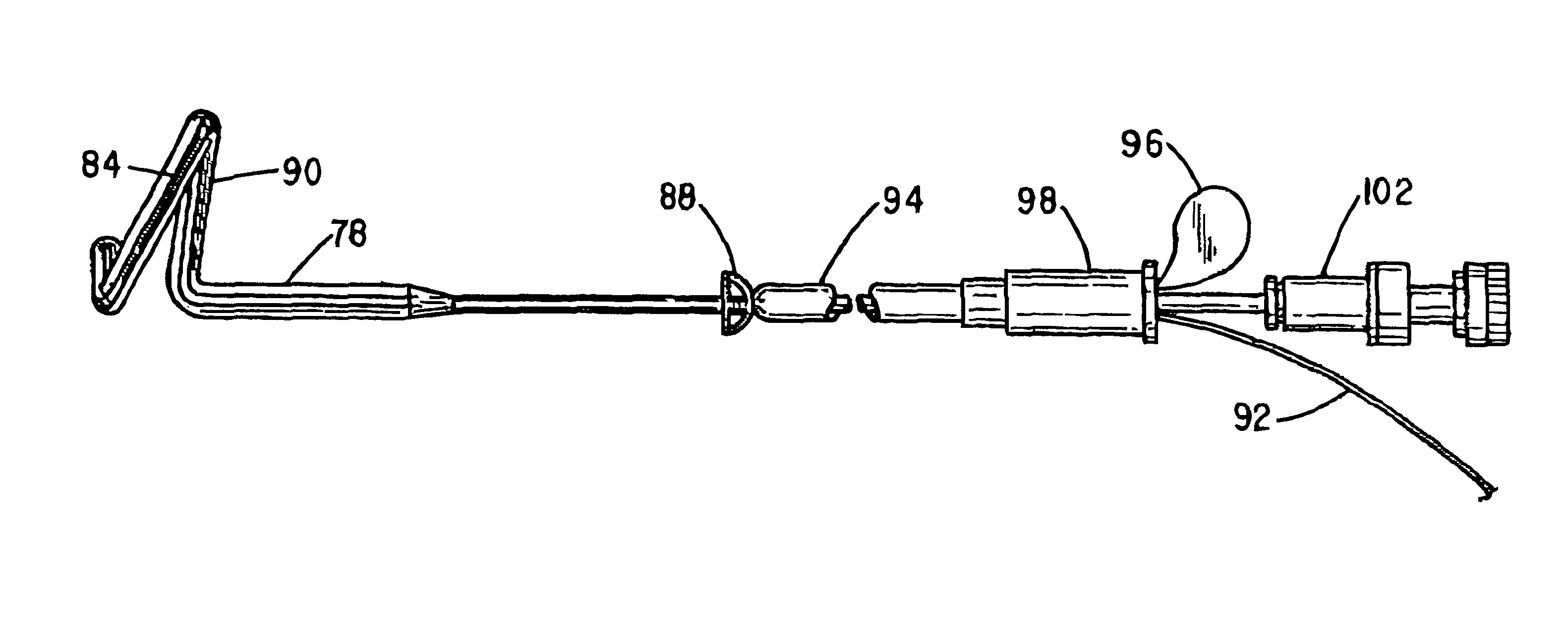
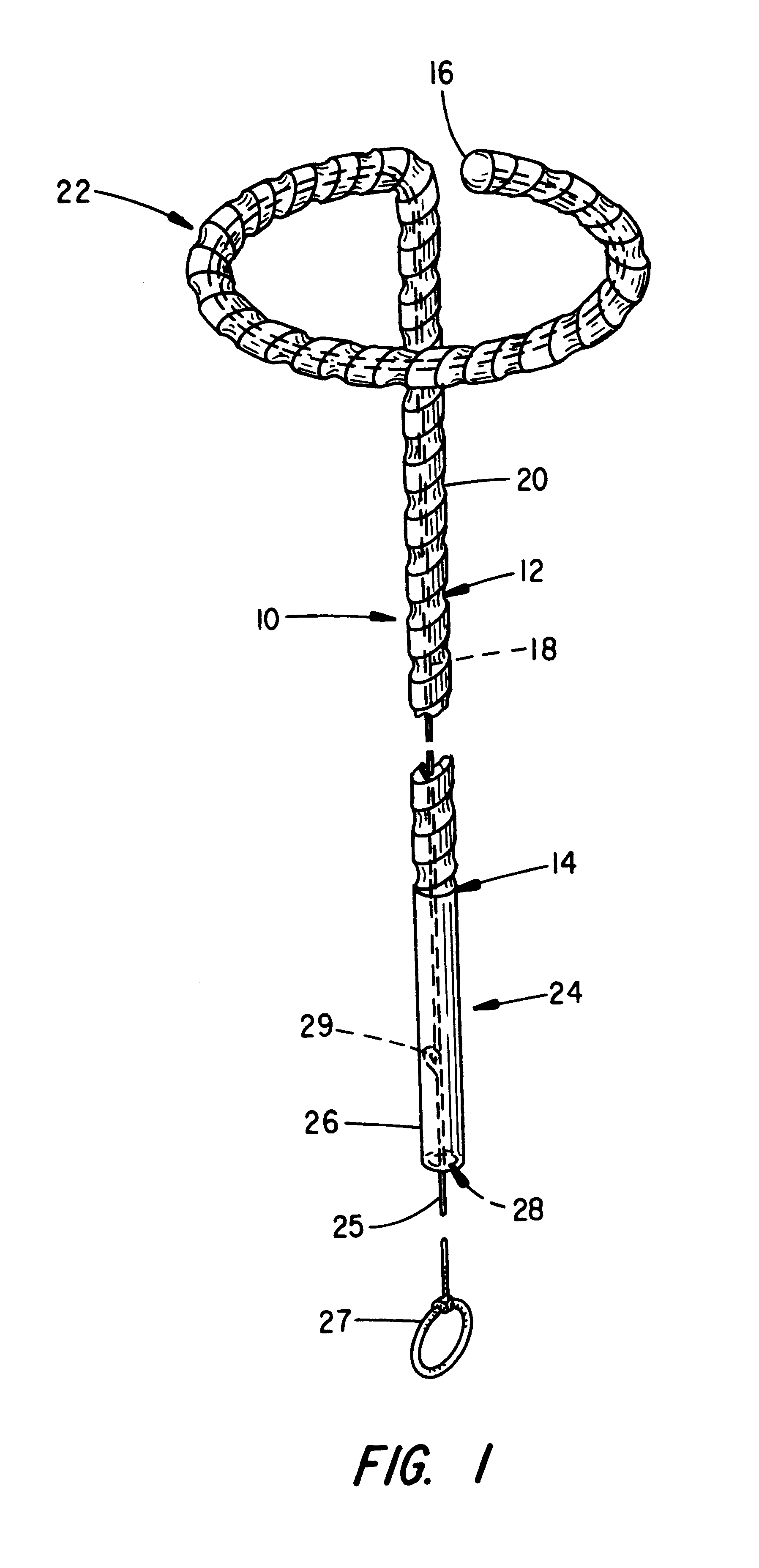
Referring to FIG. 16, there is indicated generally by numeral 76 a urinary drain comprising an alternative embodiment to the present invention. It is seen to comprise an elongated, flexible tubular body member 78 having a proximal end 80 and a distal end 82 with a stylet receiving lumen (not shown) extending from the proximal end 80 toward but just short of the distal end 82. Thus, the distal end 82 covers the stylet lumen, precluding the flow of body fluids therethrough when the drainage device 76 is appropriately placed within the urinary tract of the patient.

The body member 78 of the drainage device 76 is shown as including at least one channel 84 formed in the surface thereof and it extends from the distal end 82 to a zone 86 where the outside diameter of the drain body member 78 tapers to a lesser diameter where the drain body is void of any surface groove. As with the embodiment of FIG. 1, the drain body member 78 may have an outside dimension of about 0.21 inches in the porti...


PUM


Abstract

An urethral drain having deep external drainage channels, a low-profiled bladder retention segment, and a reversibly detachable collection segment, facilitates the draining of urine and fluids from the bladder. The low-profiled retention means minimizes bladder irritations and the deep external channels reduce the occurrence of infections. Incorporation of a reduced diameter smooth segment on the catheter, proximate the location of the external urethral sphincter allows the patient to void normally and at will. Modifying the size of this smooth segment aids the function of a defective sphincter in controlling urine leakage. The drain can be worn concealed within the urethra. Flushing action from normal voiding washes out particulate matters in the urethra and the concealed drain further minimizes contamination. Together, these features improve quality of life for patients needing catheterization.

Description

1. Field of the InventionThis invention relates generally to body fluid drainage devices, and more particularly to a urinary drain having improved performance characteristics.2. Discussion of the Prior ArtUrethral catheters, such as the Foley catheter, now used for bladder drainage are essentially elongated tubular structures placed in the urethra for draining urine through the central lumen thereof. Near the distal end of the tube is an inflatable balloon which, when inflated while in the bladder, allows the catheter to be held in place. Its proximal end has a drainage port as well as a balloon inflation port. The proximal end of the catheter protrudes beyond the urethral orifice and can be attached to a bag receptacle for the collection of the near constantly dripping urine from the bladder. The collection bag is either-attached to the patient's leg when the patient is ambulatory, or to the side of the bed during bed rest. At times, a plug is used in place of the bag to stop the l...

Claims


Application Information

Patent Timeline
IPC IPC(8): A61F2/06A61F2/04A61F2/82A61M3/00
CPCA61F2/04A61F2/82A61M27/008A61F2002/047A61M2025/0019
Inventor TIHON, CLAUDE
Owner CONSERT INC
Why Eureka
Try Eureka