Elevator door device and installation method of elevator door
An installation method and elevator door technology, applied to elevators, transportation and packaging in buildings, etc., can solve problems such as abnormal noise equipment, long time adjustment, failure and other problems, and achieve the effect of cost avoidance and appropriate clearance.
- Summary
- Abstract
- Description
- Claims
- Application Information
AI Technical Summary
Problems solved by technology
Method used
Image
Examples
Embodiment approach 1
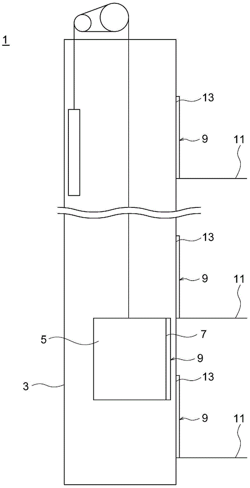
[0028] figure 1 It is a schematic diagram showing the overall structure of an elevator to which the elevator door apparatus of the present invention is applied. The elevator 1 includes a hoistway 3 extending up and down, and a car 5 provided so as to be movable in the hoistway 3 .
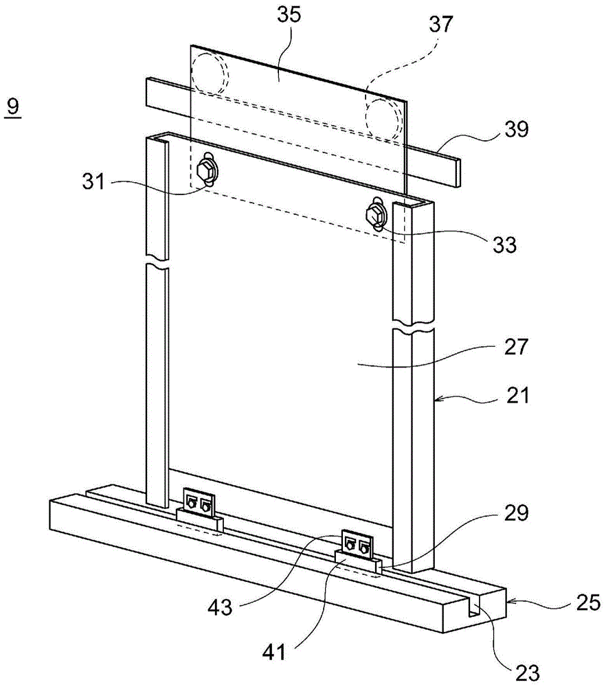
[0029] A car doorway 7 for passengers to enter and exit is provided at the front portion of the car 5 , and the car doorway 7 is opened and closed by a door device 9 . In addition, in the multi-storey landing 11 having the structure of the hoistway 3 , a landing doorway 13 is provided so as to face the car doorway 7 through the landing of the car 5 . The hall entrance 13 is also opened and closed by the door device 9 . In addition, the door device 9 of the car 5 and the door device 9 of the hall 11 are different in details or parts other than the parts related to the present invention described below, but the parts constituting the present invention will be described as the same parts.
[0030] ...
Embodiment approach 2
[0042] Next, Embodiment 2 of the present invention will be described. Figure 6 It is about this embodiment 2 and image 3 Figures of the same shape. In addition, this Embodiment 2 is the same as the said Embodiment 1 except the part demonstrated below.
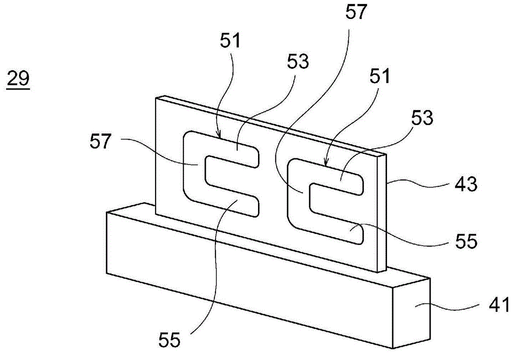
[0043] Such as Figure 6 As shown, the door shoe 129 in the second embodiment is also provided with at least one (two in the illustration) support hole portions 151 formed in the support portion 43 . The support hole portion 151 is a long hole extending in the height direction. Bolts 45 , which are fastening members for fixing the door shoe 29 to the door panel 27 , are also inserted through the support holes 151 , and the bolts 45 function as load bearing members and fixing members similarly to the first embodiment.
[0044] The bolt 45 is arranged at the relatively upper part in the elongated hole which is the support hole portion 151 at the tentative fastening position, and is arranged at the relatively lower part in t...
Embodiment approach 3
[0047] Next, Embodiment 3 of the present invention will be described. Figure 7 and Figure 8 Respectively about this Embodiment 3 and image 3 and Figure 5 Figures of the same shape. In addition, this third embodiment is the same as the above-mentioned first embodiment except for the parts described below.
[0048] Such as Figure 7 As shown, the door shoe 229 in the third embodiment is also provided with at least one (one in the illustration) support hole portion 251 . The support hole portion 251 includes at least one (one in the illustrated example) temporary support hole 61 through which a load supporting member is inserted and at least one (two in the illustrated example) fixing holes 63 through which a fixing member is inserted. Such as Figure 8 As shown, the load bearing member is a temporary support member 65 whose lower surface abuts against the sill 25 . In addition, the temporary support member 65 is a block-shaped member. In addition, on one end side of ...
PUM
 Abstract
Description
Claims
Application Information
 - R&D
- Intellectual Property
- Life Sciences
- Materials
- Tech Scout
- Unparalleled Data Quality
- Higher Quality Content
- 60% Fewer Hallucinations
Browse by: Latest US Patents, China's latest patents, Technical Efficacy Thesaurus, Application Domain, Technology Topic, Popular Technical Reports.
© 2025 PatSnap. All rights reserved.Legal|Privacy policy|Modern Slavery Act Transparency Statement|Sitemap|About US| Contact US: help@patsnap.com


