Light modulation driving circuit and illumination apparatus comprising the light modulation driving circuit

A dimming drive and lighting device technology, which is applied to lighting devices, lamp circuit layout, electroluminescent light sources, etc., can solve the problems of increasing the consumption of the discharge circuit, the power loss of the lighting device, and increasing the power consumption of the integrated circuit.

Active Publication Date: 2015-10-14
OSRAM GMBH
View PDF4 Cites 0 Cited by
  • Summary
  • Abstract
  • Description
  • Claims
  • Application Information

AI Technical Summary

Problems solved by technology

However, the existing driving device with the function of phase-cut dimming increases the consumption of the bleeder circuit because it is connected to the dimmer, and thus increases the power consumption of the entire integrated circuit, which brings unnecessary waste to the lighting device. power loss

Method used


Image

  • Light modulation driving circuit and illumination apparatus comprising the light modulation driving circuit
  • Light modulation driving circuit and illumination apparatus comprising the light modulation driving circuit

Examples


Embodiment Construction

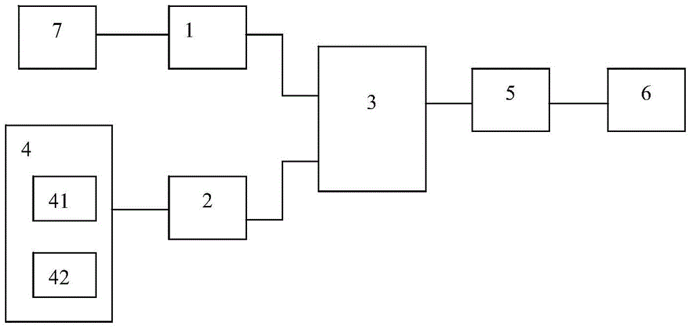
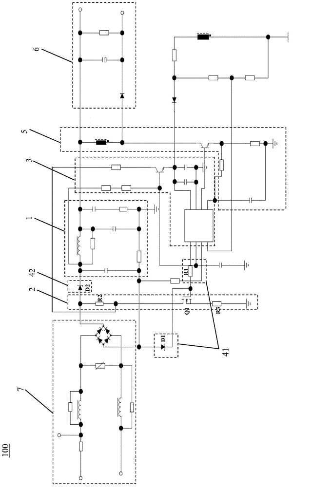
[0018] figure 1 A schematic functional block diagram of the dimming driving circuit 100 according to the present invention is shown. Such as figure 1 As shown, the dimming driving circuit 100 according to the present invention includes a main control module 3 , a filter circuit unit 1 and a bleeder circuit unit 2 connected to the main control module 3 . The main control module 3 can be designed as an integrated circuit or a central controller integrated with a leading edge dimmer and a trailing edge dimmer, wherein the leading edge dimmer has a leading edge phase dimming function, and the trailing edge dimmer has a trailing edge dimming function. Along phase dimming function. In addition, the dimming drive circuit 100 also includes a power conversion unit 5 connected to the main control module 3, an input module 7 connected to the filter circuit unit 1, an output module 6 connected to the power conversion module 5, and a discharge circuit connected to Auxiliary control modu...


PUM


Abstract

The present invention relates to a dimming drive circuit for an illumination apparatus and an illumination apparatus comprising the dimming drive circuit, wherein the dimming drive circuit comprises a filter circuit unit and a bleeder circuit unit, and a main control module connected to the filter circuit unit and the bleeder circuit unit, respectively, wherein the dimming drive circuit further comprises an auxiliary control module configured to reduce the current of the bleeder circuit unit and / or to switch off the bleeder circuit unit according to a characteristic input current of the dimming drive circuit prior to switch-off of the bleeder circuit unit by the main control module in a first operation state of the dimming drive circuit, and to prevent the filter circuit unit from releasing electrical energy via the bleeder circuit unit in a second operation state of the dimming drive circuit.

Description

technical field [0001] The invention relates to a dimming driving circuit for an illuminating device and an illuminating device comprising the dimming driving circuit. Background technique [0002] In an existing driving device of an illuminating device, a phase-cut dimming method is usually used to control the dimming of the illuminating device. The lighting device that controls the dimming according to the phase-cut dimming method can not only effectively and quickly control the luminous brightness of the lighting device, but also save power to a certain extent, and because the structure of the driving device with the phase-cut dimming function is simple, Manufacture is simple and has low cost. The driving device with the phase-cut dimming function not only has a high power factor, but also is compatible with the leading phase-cutting dimming circuit or the trailing-cutting phase dimming circuit. Additionally, the drive can operate in Quick Response (QR) mode, or in Buck...

Claims


Application Information

Patent Timeline
Patent Type & Authority Applications(China)
IPC IPC(8): H05B37/02H05B44/00
CPCH05B33/0845H05B37/02H05B45/10H05B47/10H05B45/3575H05B45/31H05B45/315
Inventor 肖海斌董玉磊
Owner OSRAM GMBH
Why Eureka
Try Eureka