Round valve tray

A floating valve tray and circular technology, applied in chemical/physical/physical chemical processes, chemical instruments and methods, chemical/physical processes, etc., can solve the problem of unsatisfactory handling of air flow by float valves, insufficient gas-liquid contact, Problems such as irregular airflow rise to achieve the effect of reducing the amount of mist entrainment, fine and uniform airflow dispersion, and promoting continuous renewal

Active Publication Date: 2017-04-12
SUZHOU RUNHONG TRADING
View PDF5 Cites 2 Cited by
  • Summary
  • Abstract
  • Description
  • Claims
  • Application Information

AI Technical Summary

Problems solved by technology

[0005] At present, although the floating valve tray has been greatly improved in terms of operating flexibility, in production, the applicant found that in industrial production, the air flow rises irregularly, resulting in unsatisfactory treatment of the air flow by the float valve and uneven dispersion of the air flow and insufficient gas-liquid contact

Method used


Image

  • Round valve tray
  • Round valve tray
  • Round valve tray

Examples


Embodiment

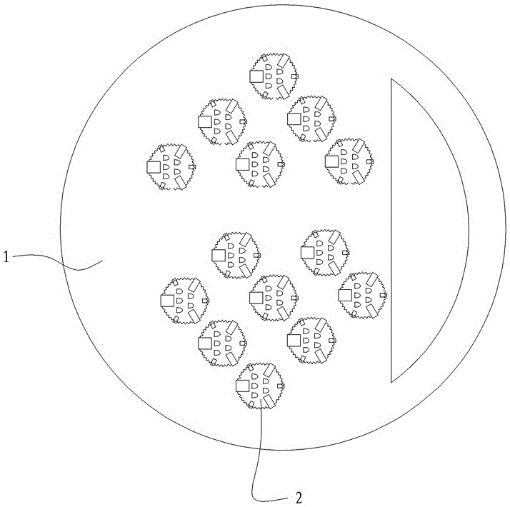
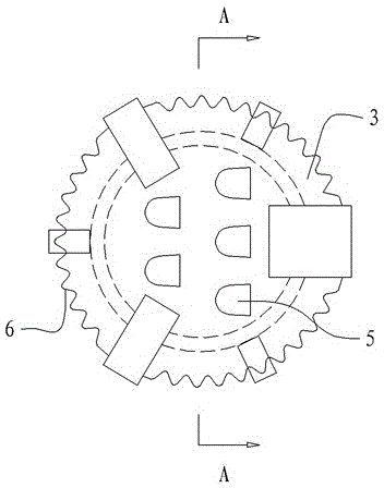
[0019] The circular valve tray of the present embodiment, such as Figure 1 to Figure 4 As shown, it includes a tray 1 and a float valve 2 that can move up and down. The tray 1 is formed with an installation hole for the installation of the float valve. The float valve 2 includes a circular valve cover 3 arranged above the tray 1 and a valve leg 4 extending downward from the periphery of the valve cover to the bottom of the tray. The valve legs 4 are distributed at intervals along the periphery of the valve cover 3 .

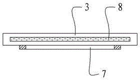
[0020] The valve cover 3 is provided with at least two upwardly arched tongue holes 5, and the periphery of the valve cover 3 is provided with a downwardly folded serrated edge 6, which is used to abut against the tower when the float valve 2 falls. plate 1 upper surface.

[0021] A ring of protrusions 7 is fixed on the bottom surface of the valve cover 3 , and the tongue hole 5 is located in the ring of protrusions 7 of the valve cover 3 . The circle of prot...


PUM


Abstract

The invention relates to a circular float valve tray, and belongs to the technical field of general physical separation devices. The circular float valve tray comprises a tower plate and float valves capable of moving up and down, wherein mounting holes used for the mounting of the float valves are formed in the tower plate; each float valve comprises a circular valve cap arranged above the tower plate and valve legs extending downwards from the periphery of the valve cap to the lower part of the tower plate; the valve legs are distributed on the periphery of the corresponding valve cap at intervals; at least two upwards arched tongue holes are formed in each valve cap; downwards bent sawtooth-shaped edges are arranged on the periphery of each valve cap, and are used for being propped against the upper surface of the tower plate when the corresponding float valve falls down; a lap of bumps are fixed on the bottom surface of each valve cap; the tongue holes are positioned within the lap of bumps of the corresponding valve cap; an interlayer cavity is formed in each valve cap and is filled with a polystyrene foam layer. The circular float valve tray has the advantages that the dispersion of airflow is fine and uniform, and the full contact of gas and liquid is realized.

Description

technical field [0001] The invention relates to a tray, which belongs to the technical field of general physical separation operation devices. Background technique [0002] Floating valve tower is a new type of tower with simple structure, low manufacturing cost, and can adapt to common material conditions. It is one of the most widely used tower types in chemical and oil refining industries. The performance and technical level of the tower equipment in the valve tower directly affect the output, quality, recovery rate, economic benefits and other aspects of the product. [0003] The float valve tower is characterized by installing a float valve that can move up and down at each mounting hole. When the gas velocity in the installation hole is high, the float valve is lifted up, and when the air velocity is low, the float valve will drop due to its own weight. The lifting position of the float valve is automatically adjusted with the gas flow, so that the gas velocity enter...

Claims


Application Information

Patent Timeline
Patent Type & Authority Patents(China)
IPC IPC(8): B01J19/32
Inventor 徐萍
Owner SUZHOU RUNHONG TRADING
Why Eureka
Try Eureka