Heat exchanger, in particular for a refrigerant circulating in a motor vehicle

A technology for heat exchangers and motor vehicles, applied in the field of exchangers, can solve the problems of not improving heat exchange efficiency and increasing the cost of exchangers

Active Publication Date: 2015-10-21
VALEO SYST THERMIQUES
View PDF6 Cites 3 Cited by
  • Summary
  • Abstract
  • Description
  • Claims
  • Application Information

AI Technical Summary

Problems solved by technology

Therefore, they increase the cost of the exchanger due to the quality of the material used (msaamass), but do not improve the efficiency of the heat exchange

Method used


Image

  • Heat exchanger, in particular for a refrigerant circulating in a motor vehicle
  • Heat exchanger, in particular for a refrigerant circulating in a motor vehicle
  • Heat exchanger, in particular for a refrigerant circulating in a motor vehicle

Examples


Embodiment Construction

[0037] In the following description, the same reference numerals are used to designate the same or similar elements.

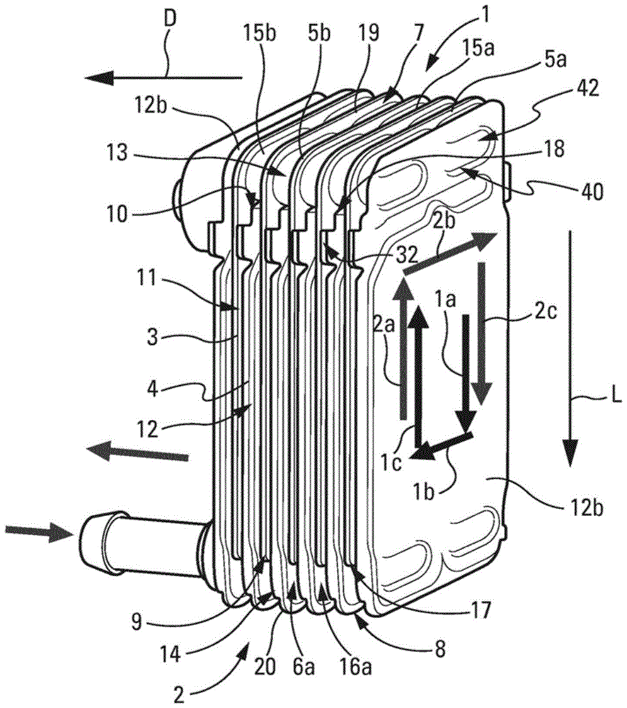
[0038] as in figure 1 with 2 As illustrated in , the invention relates to heat exchangers, in particular for refrigerants circulated in motor vehicles.

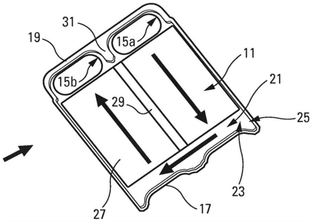
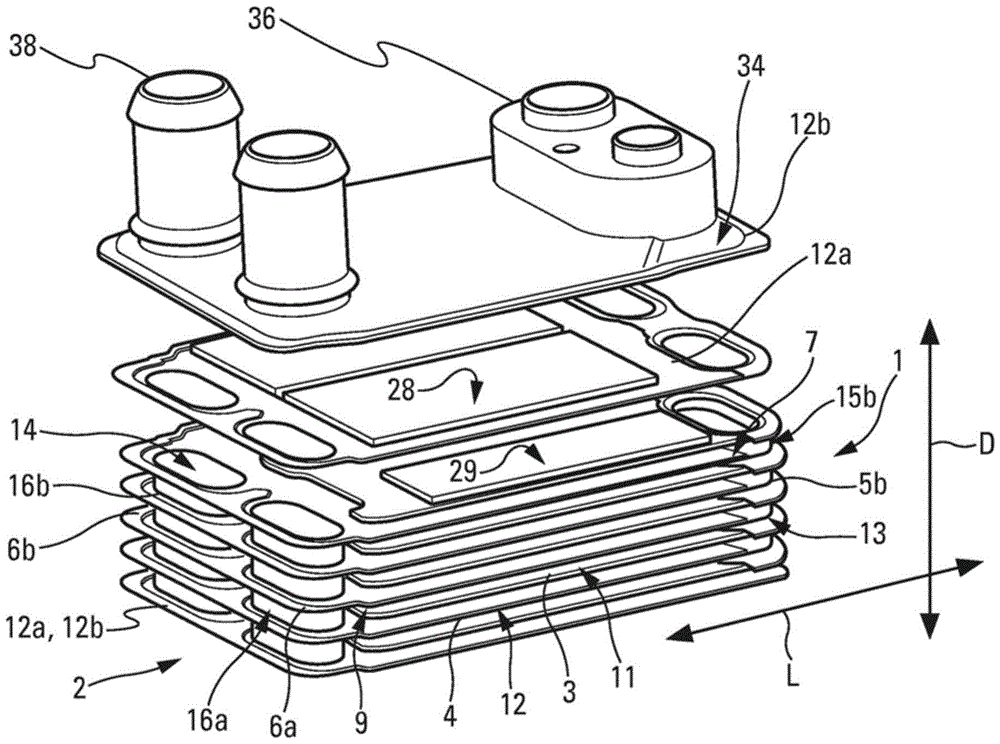
[0039] Said exchanger comprises a first unit 1 for circulating a first fluid, and a second unit 2 for circulating a second fluid, said first unit defining first vanes 3 for circulating said first fluid, Said second unit defines second vanes 4 for circulating said second fluid. The blades 3 , 4 are stacked in the stacking direction D of the blades so that heat exchange can take place between the first fluid and the second fluid.

[0040] The units 1 , 2 are formed, for example, from parts made of aluminum and / or aluminum alloys. They can be assembled, for example by brazing of the parts.

[0041] exist figure 1 In the above, the first unit 1 extends from the top to the bottom, and the second unit 2 exten...


PUM


Abstract

The invention relates to a heat exchanger, in particular for a refrigerant circulating in a motor vehicle, said heat exchanger comprising a first unit (1) for circulating a first fluid, defining first blades (3) for circulating said first fluid, and a second unit (2) for circulating a second fluid, defining second blades (4) for circulating said second fluid, wherein said blades (3, 4) are stacked in a stacking direction such that heat exchange can take place between the first and second fluids and said units (1, 2) allow the first fluid to circulate while avoiding the second unit (2), and the second fluid to circulate while avoiding the first unit (1).

Description

technical field [0001] The invention relates to an exchanger. Although the exchanger is more specifically intended for application as an internal exchanger of an air-conditioning circuit or as an exchanger between a refrigerant and a heat transfer fluid, it can also be utilized more broadly for any type of fluid between two fluids. heat exchange. Background technique [0002] Various configurations of exchangers defining circulation blades for each fluid between which heat exchange needs to take place are known in the art. Particularly well known are brazed exchangers in which the blades are defined by stacked plates between which circulation blades are alternately defined. The blades for fluid circulation are joined together by connecting elements discharging in the area of ​​the channel openings, which are likewise arranged in the plate, in such a way that each fluid from its circulation blade One travels to the other without penetrating into the circulation blades of t...

Claims


Application Information

Patent Timeline
Patent Type & Authority Applications(China)
IPC IPC(8): F28D7/00F25B40/00F28D9/00
CPCF28D7/0025F28D9/0043F28D9/005F28D9/0056F28D9/00F28F9/02
Inventor C.德诺瓦尔A.波尔马林F.蒂森
Owner VALEO SYST THERMIQUES
Why Eureka
Try Eureka