Heat exchanger and associated heat exchange system for a vehicle

A heat exchange system and heat exchanger technology, applied in the field of heat exchange systems, can solve the problems of limiting the size of the system, complex manufacturing and implementation of the heat exchange system, etc.

Pending Publication Date: 2022-02-22
VALEO SYST THERMIQUES
View PDF8 Cites 0 Cited by
  • Summary
  • Abstract
  • Description
  • Claims
  • Application Information

AI Technical Summary

Problems solved by technology

Therefore, the use of storage bottles in the prior art requires many mechanical devices, which limit the size of the system and complicate the manufacture and implementation of the heat exchange system on the vehicle

Method used


Image

  • Heat exchanger and associated heat exchange system for a vehicle
  • Heat exchanger and associated heat exchange system for a vehicle
  • Heat exchanger and associated heat exchange system for a vehicle

Examples


Embodiment Construction

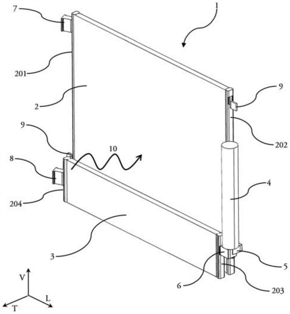
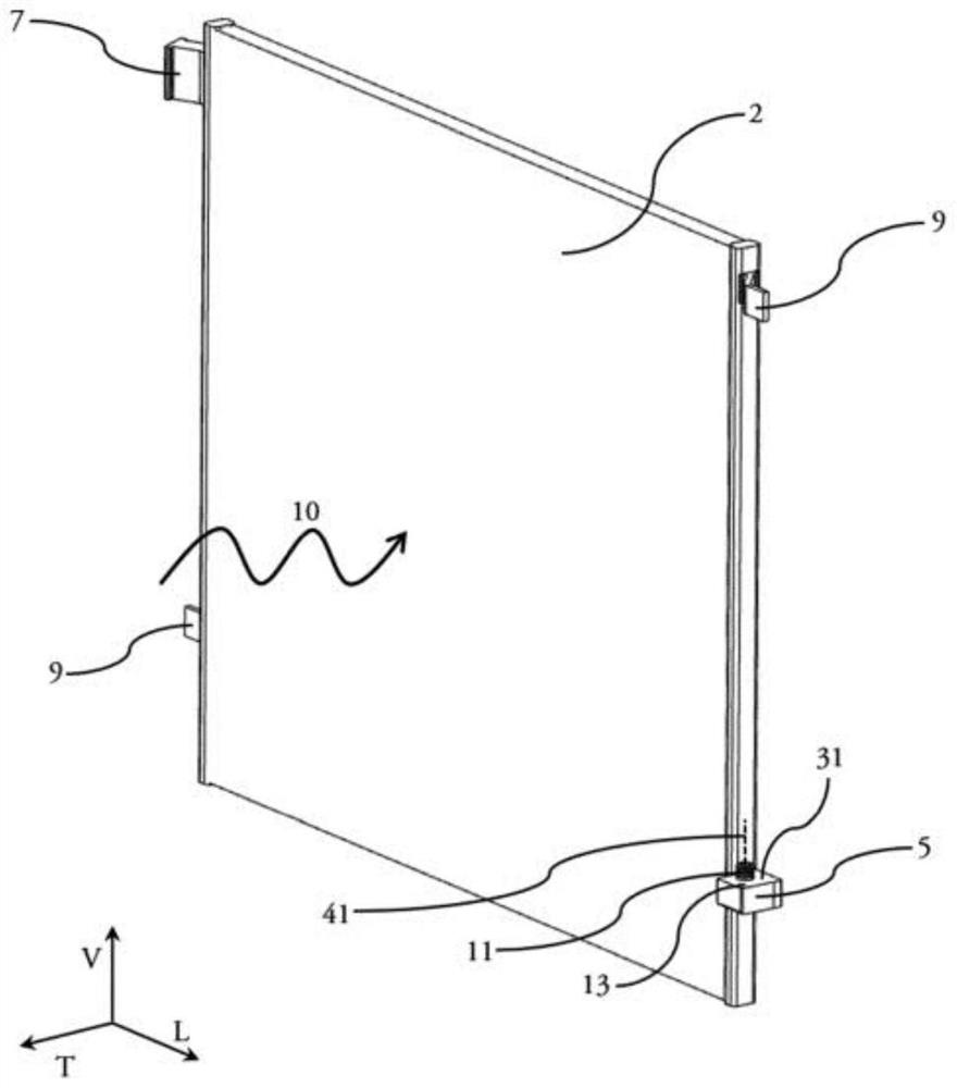
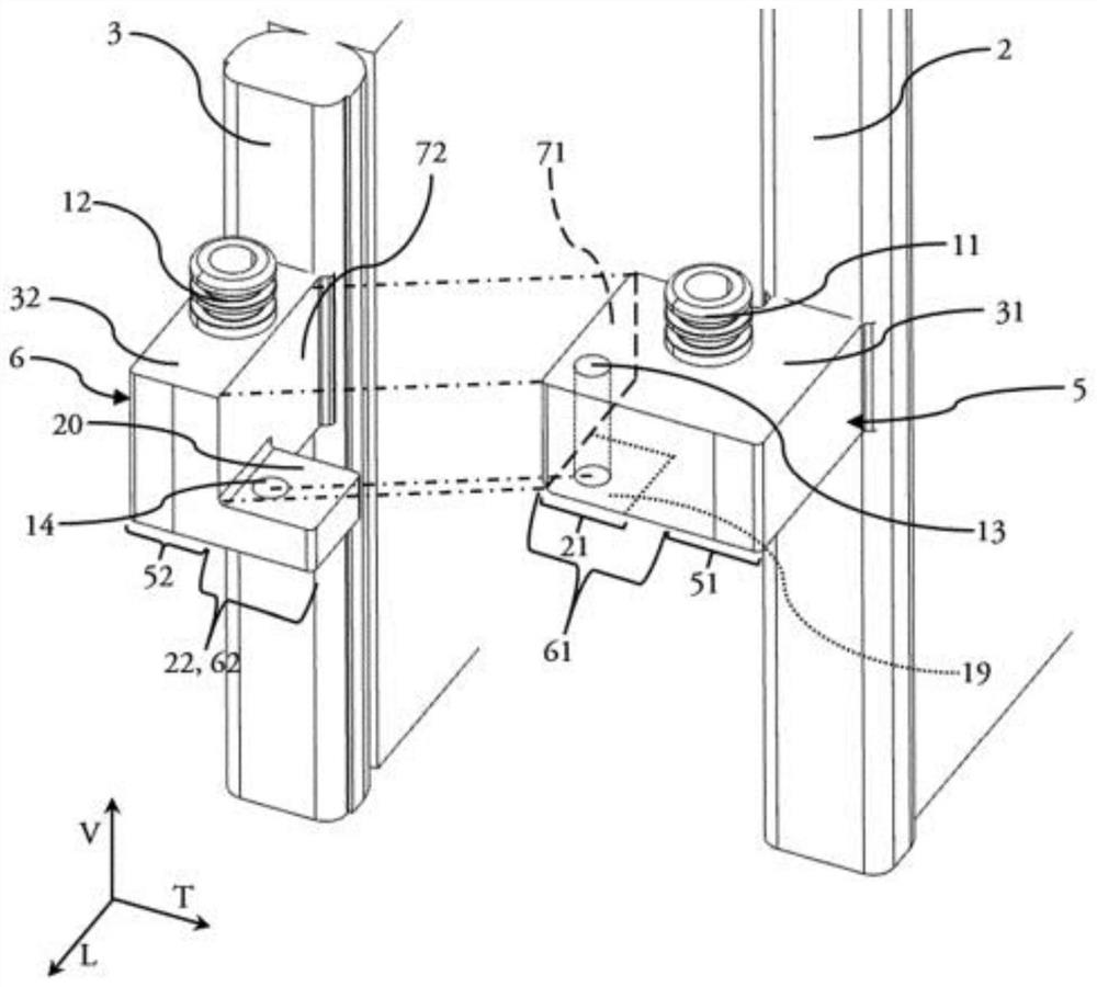
[0040] For the clarity of the detailed description of the connecting flanges, the LVT frame of reference will represent the orientation of the heat exchange system according to the invention. The longitudinal direction L and the vertical direction V correspond to axes parallel to the two intersecting straight lines defining the elongate plane of the heat exchanger according to the invention, the transverse direction T corresponds either to an axis perpendicular to one of the directions L or V, or Corresponds to the axis parallel to the airflow forced through the heat exchange system.

[0041] In addition, the terms "first" and "second" mentioned in the description have no quantitative or ordering meaning, but are only used to distinguish certain elements that appear repeatedly in the present invention. An element present in duplicate in the present invention but not introduced by the term "first" or "second" designates equivalently one or the other element in duplicate.

[00...


PUM


Abstract

The invention relates to a heat exchanger (2, 3) for a coolant circulation circuit comprising at least one connection flange (5, 6) attached to a side surface of said heat exchanger (2, 3), characterised in that the connection flange (5, 6) comprises a circulation channel inside the structure thereof and a transverse mechanical attachment zone (21, 22) able to engage with another transverse mechanical attachment zone (21, 22) of another connection flange (5, 6) of another heat exchanger (2, 3). The invention likewise claims a heat exchange system for a vehicle comprising two such heat exchangers (2, 3), the respective connection flanges (5, 6) of which are able to engage with one another.

Description

technical field [0001] The present invention relates to a heat exchange system arranged on a fluid distribution circuit, the heat exchange system comprising at least one plurality of heat exchangers, each heat exchanger being able to Heat exchange occurs between the circulating fluids. Background technique [0002] It is known to arrange such a heat exchange system on the front surface of the vehicle, said system notably comprising a condenser capable of ensuring a good communication between the refrigerant circulating in the condenser and the incoming flow of fresh air from outside the vehicle. heat exchange. It is known to make a condenser as a single piece with a series of stacked plates, between which are formed, on the one hand, sealed flow ducts for the passage of the refrigerant and, on the other hand, for the passage of the air channel. [0003] Known arrangements include arranging a first heat exchanger as a condenser, and arranging a second heat exchanger parall...

Claims


Application Information

Patent Timeline
Patent Type & Authority Applications(China)
IPC IPC(8): F28D21/00F28F9/18F28F9/26F28F9/22
CPCF28D21/00F28F9/18F28F9/26F28F9/22F28D2021/008F28D1/0426F28D1/05366F28D2021/0084F28F9/002F28F9/0251F28F9/262F25B39/04F28D1/0435F28D1/05383
Inventor R.图尔诺伊斯F.比罗德J.特林达德
Owner VALEO SYST THERMIQUES
Why Eureka
Try Eureka