A self-adjusting hydraulic brake caliper assembly

A hydraulic braking and self-adjusting technology, which is applied in the field of brake calipers, can solve the problems of small return stroke, large brake disc end face jump, failure, etc., to achieve the effect of controlling the braking distance and ensuring the braking effect

Active Publication Date: 2017-09-22
WUHU WENLE BRAKING SYST
View PDF7 Cites 0 Cited by
  • Summary
  • Abstract
  • Description
  • Claims
  • Application Information

AI Technical Summary

Problems solved by technology

[0002] At present, there are two main types of suspension hydraulic brake calipers used in agricultural machinery equipment: one is to control the piston travel distance through a rectangular ring, so as to achieve the purpose of self-adjustment. The advantage of this brake caliper is that it can automatically ensure two The gap between the brake pad and the friction disc, but because the braking and return stroke of the rectangular ring is too small and the end face of the brake disc itself has a large jump, the brake pad is always close to the brake disc, so that the friction of the friction disc The temperature rises sharply and burns, which obviously reduces the service life and braking efficiency of the friction plate; the other is to forcibly pull the piston brake plate back by the external force of the spring, and the piston is pulled back to the same original position every time. The advantage of the moving caliper is to make up for the defects of the former brake caliper, but with the wear of the brake pads, the braking gap increases continuously, the braking effect decreases or fails, and the braking distance becomes larger or lost

Method used


Image

  • A self-adjusting hydraulic brake caliper assembly
  • A self-adjusting hydraulic brake caliper assembly

Examples


Embodiment Construction

[0020] The specific implementation manner of the present invention will be described in further detail below by describing the embodiments with reference to the accompanying drawings.

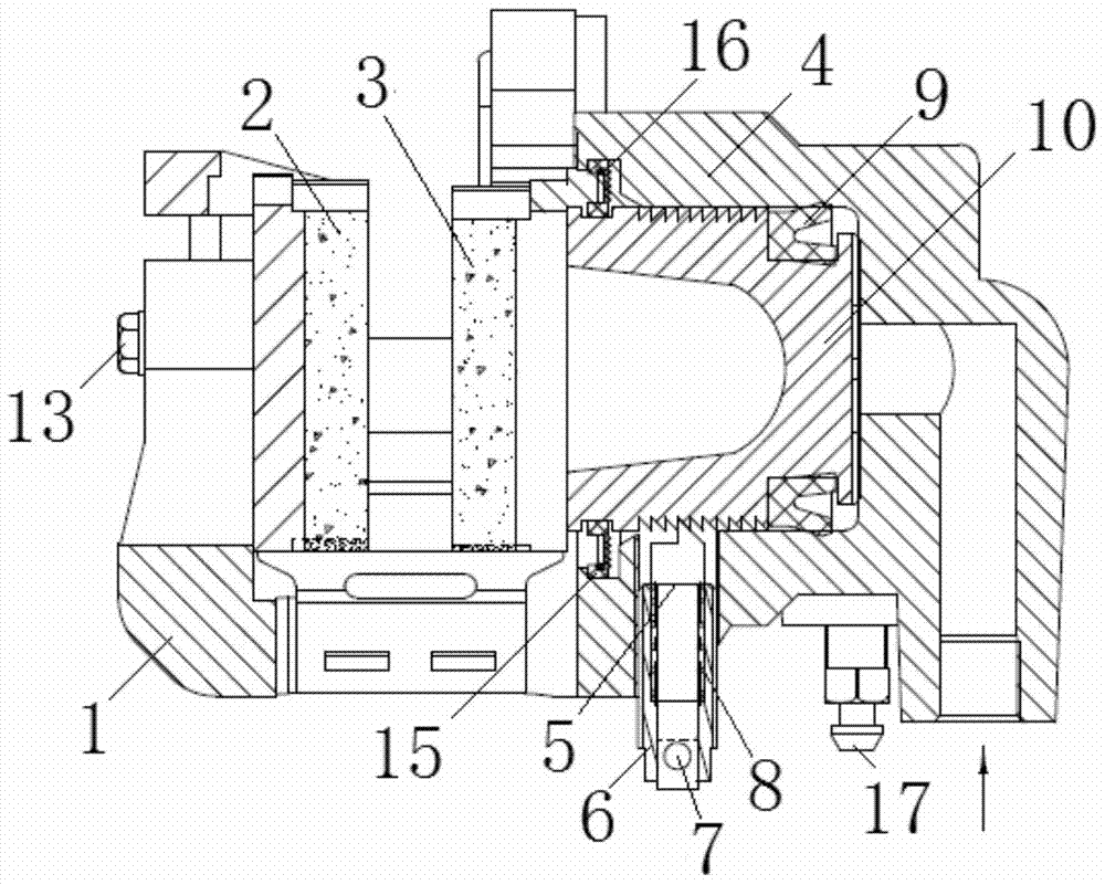
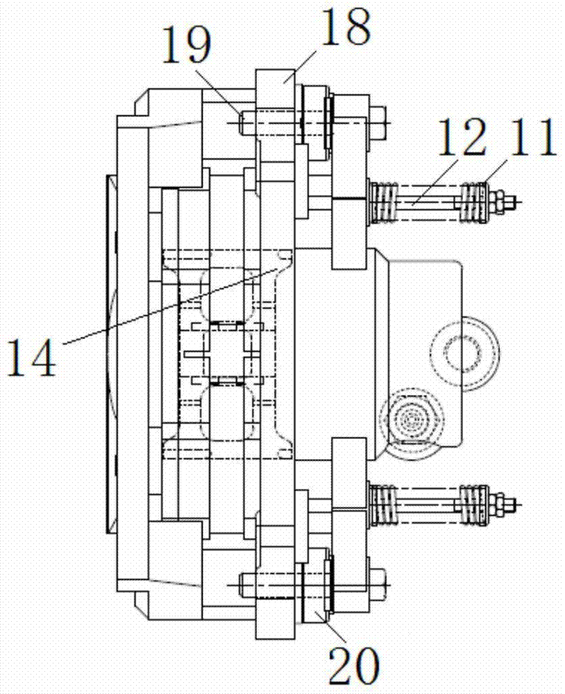
[0021] Such as figure 1 and figure 2 As shown, the self-adjusting hydraulic brake caliper assembly includes a caliper body 1, a bracket 18 and a self-adjusting mechanism, wherein the caliper body 1 is provided with dynamic friction plates 3 and static friction plates 2 located on both sides of the brake disc, and the caliper There is a hydraulic cylinder 4 on one side of the moving friction plate on the body, and a piston 10 is arranged inside the hydraulic cylinder 4, and a double-lip apron 9 is installed on the inner end of the piston, and the piston is pushed to the side under the pressure of the transmission fluid. Movement in the direction of the cylinder mouth pushes the dynamic friction plate to the brake disc. At the same time, the reaction force moves the caliper body backward, and t...


PUM


Abstract

The invention discloses a self-adjusting type hydraulic brake caliper assembly. The self-adjusting type hydraulic brake caliper assembly comprises a caliper body, a static friction plate and a dynamic friction plate opposite to the static friction plate are arranged in the caliper body, and the dynamic friction plate is connected with the outer side of a piston movably arranged in the caliper body. A pin shaft, a shaft sleeve and a compression spring are further included. The shaft sleeve is arranged on the caliper body, one end of the pin shaft is connected with the shaft sleeve through the compression spring, and the other end of the pin shaft matches an inclined ratchet arranged on the piston. The ratchet outside a piston body matches the pin shaft with the compression spring to form a self-adjusting mechanism, the piston is controlled to reset, and it is guaranteed that the piston is within the required range always. The aim of automatically adjusting the clearance between the static friction plate and the dynamic friction plate is achieved, the brake distance is controlled, and the brake effect is guaranteed.

Description

technical field [0001] The invention relates to the technical field of brake caliper, in particular to a self-adjusting hydraulic brake caliper assembly. Background technique [0002] At present, there are two main types of suspension hydraulic brake calipers used in agricultural machinery equipment: one is to control the piston travel distance through a rectangular ring, so as to achieve the purpose of self-adjustment. The advantage of this brake caliper is that it can automatically ensure two The gap between the brake pad and the friction disc, but because the braking and return stroke of the rectangular ring is too small and the end face of the brake disc itself has a large jump, the brake pad is always close to the brake disc, so that the friction of the friction disc The temperature rises sharply and burns, which obviously reduces the service life and braking efficiency of the friction plate; the other is to forcibly pull the piston brake plate back by the external forc...

Claims


Application Information

Patent Timeline
Patent Type & Authority Patents(China)
IPC IPC(8): F16D65/092F16D65/44
CPCF16D65/092F16D65/44
Inventor 潘高峰张建华
Owner WUHU WENLE BRAKING SYST
Why Eureka
Try Eureka