Rail train brake control method and device

A rail train and braking control technology, which is applied in the field of rail trains, can solve problems such as loss of braking force of rail trains, difficulty in effectively controlling the braking distance of rail trains, and threats to the safe operation of rail trains.

Active Publication Date: 2020-04-03
QINGDAO SRI TECH CO LTD
View PDF6 Cites 7 Cited by
  • Summary
  • Abstract
  • Description
  • Claims
  • Application Information

AI Technical Summary

Problems solved by technology

As a result, the rail train loses part of its braking force, making it difficult to effectively con

Method used


Image

  • Rail train brake control method and device
  • Rail train brake control method and device
  • Rail train brake control method and device

Examples


Embodiment Construction

[0045] In order to make the purpose, technical solutions and advantages of the embodiments of the present invention clearer, the technical solutions in the embodiments of the present invention will be clearly and completely described below in conjunction with the drawings in the embodiments of the present invention. Obviously, the described embodiments It is a part of embodiments of the present invention, but not all embodiments. Based on the embodiments of the present invention, all other embodiments obtained by persons of ordinary skill in the art without making creative efforts belong to the protection scope of the present invention.

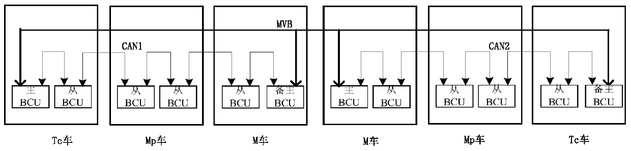
[0046] see figure 1 , figure 1 It is a schematic diagram of the network structure of the rail train braking control system. As shown, the network of rail train control systems includes at least one CAN unit, and in most cases, a plurality of CAN units.

[0047] In any CAN unit, including multiple BCUs, according to different specific funct...


PUM


Abstract

The invention provides a rail train brake control method and device. The method is applied to the technical field of rail trains. A obtains the total braking force of the train under the condition that the communication between the standby main BCU and the main BCU is interrupted; the standby main BCU determines a slave BCU capable of establishing communication connection to obtain a target slaveBCU, and a CAN unit controlled by the standby main BCU is constructed; train-level braking force distribution is carried out to obtain the unit braking force, then the unit braking force is sent to each target slave BCU; therefore, each BCU in the CAN unit controlled by the standby main BCU controls the corresponding brake mechanism to brake according to the obtained unit brake force. By means ofthe method, under the condition that communication with the main BCU is interrupted, the standby main BCU can still control the slave BCU capable of establishing communication connection to conduct braking, the braking force loss of the rail train can be reduced to the maximum degree, then the braking distance of the rail train is effectively controlled, and the running safety of the rail train isguaranteed.

Description

technical field [0001] The invention belongs to the technical field of rail trains, in particular to a braking control method and device for rail trains. Background technique [0002] Most of the existing rail train braking control systems use MVB (Multifunction Vehicle Bus, multifunctional vehicle bus) and CAN (Controller Area Network, controller area network) two-layer communication network for braking force control. figure 1 It is a schematic diagram of the network structure of the rail train braking control system, such as figure 1 As shown, for a 6-car train consisting of 6 car bodies, it can be divided into two CAN units, CAN1 and CAN2. In any CAN unit, multiple BCUs (Brake control units, brake control units) are included. According to different specific functions, it can be subdivided into a master BCU (Brake control unit, brake control unit), a backup master BCU and several slave BCUs. Each BCU in the same CAN unit communicates through the CAN bus and is allocated b...

Claims


Application Information

Patent Timeline
IPC IPC(8): B60T17/18
CPCB60T17/18
Inventor 罗智迅陈林罗超张一鸣高晓明
Owner QINGDAO SRI TECH CO LTD
Why Eureka
Try Eureka