Modular wind tube machine and air conditioner

A duct machine, modular technology, applied in air-conditioning systems, space heating and ventilation, space heating and ventilation details, etc. Applicable places, etc.

Active Publication Date: 2015-11-04
GD MIDEA HEATING & VENTILATING EQUIP CO LTD +1
View PDF6 Cites 13 Cited by
  • Summary
  • Abstract
  • Description
  • Claims
  • Application Information

AI Technical Summary

Problems solved by technology

Existing commonly used air duct machine, the size of the air duct machine shell is fixed and single, but the actual installation environment is complex and special, and there are many restrictions on the height or depth of the local ceiling, which seriously affects the applicable places of the air duct mach

Method used


Image

  • Modular wind tube machine and air conditioner
  • Modular wind tube machine and air conditioner
  • Modular wind tube machine and air conditioner

Examples


Embodiment 2

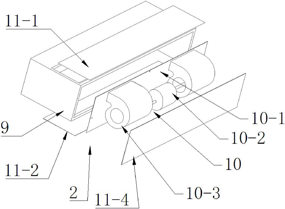
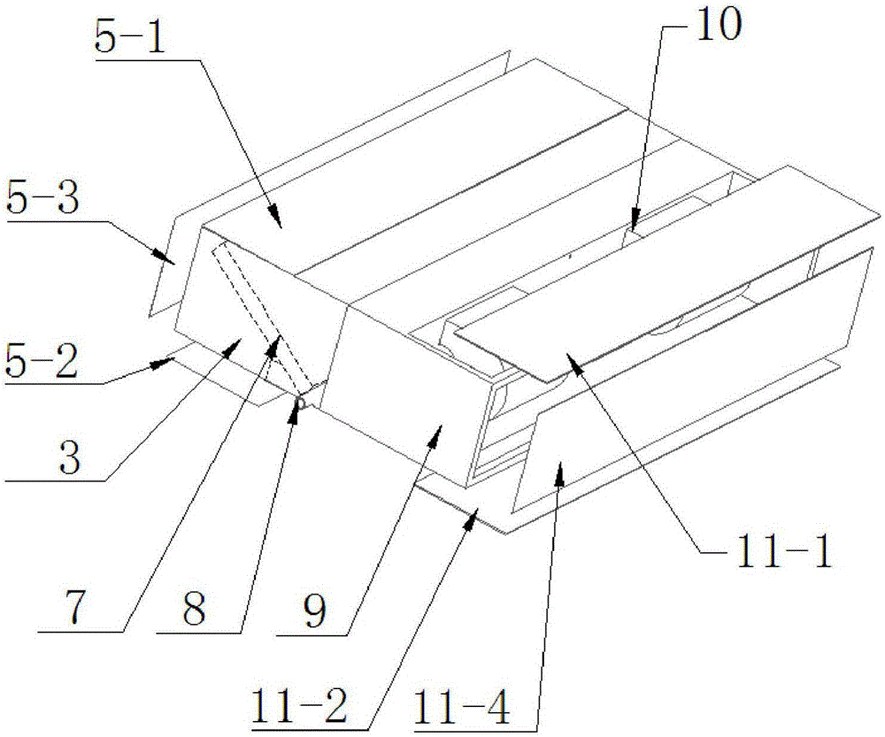
[0042] Such as Figure 5 , Figure 6 As shown, the air outlet box body 3 is rotated 180 degrees along the vertical axis, so that the air outlet box front baffle 5-3 is located at the rear end of the air outlet box body 3, and the air outlet box rear baffle 5-4 is located at the air outlet box body 3; remove the front baffle 5-3 of the air outlet box, remove the front baffle 11-3 of the air return box, and install the partition 10-1 on the front baffle 11-3 of the original air return box, so that the volute wind wheel 10-3 The air outlet of the air outlet is facing the outside of the air return box body 9, and the end face of the air outlet box body 3 provided with the opening 4 and the end face of the air return box body 9 provided with the fan assembly 10 are fixedly connected by screws. After the two are installed, the overall width is 2D, and the overall The height is H, the fan assembly 10 is fixed on the opening 4 of the air outlet box body 3 by screws or buckles, the wa...

Embodiment 3

[0044] Such as Figure 7 , Figure 8 As shown, the air outlet box body 3 is rotated 90 degrees clockwise along the horizontal axis, so that the air outlet box lower baffle 5-2 is located at the front end of the air outlet box body 3, and the air outlet box front baffle 5-3 is located at the front end of the air outlet box body 3. The upper end, the upper baffle plate 5-1 of the air outlet box is located at the rear end of the air outlet box body 3, and the rear baffle plate 5-4 of the air outlet box is located at the lower end of the air outlet box body 3; the air return box body 9 is rotated 90 degrees clockwise along the horizontal axis , so that the lower baffle plate 11-2 of the air return box is located at the front end of the air return box body 9, the front baffle plate 11-3 of the air return box is located at the upper end of the air return box body 9, and the upper baffle plate 11-1 of the air return box is located at the main body of the air return box 9, the rear e...


PUM


Abstract

The invention relates to a modular wind tube machine and an air conditioner. The modular wind tube machine comprises an air outlet module and an air returning module. The air outlet module comprises an air outlet box body; an opening is formed in one end face of the air outlet box body; air outlet box baffles are detachably installed on other end faces of the air outlet box body; a water receiving tray is arranged inside the air outlet box body; a heat exchanger is arranged above the water receiving tray; the water receiving tray is provided with a water collection tray drainage pipe enabling the water receiving tray and the outer side of the air outlet box body to be communicated. The air returning module comprises an air returning box body; a draught fan assembly is arranged on one end face of the air returning box body; air returning box baffles are detachably installed on other end faces; the draught fan assembly is arranged inside the air returning box body; the end face, with the opening, of the air outlet box body and the end face, with the draught fan assembly, of the air returning box body are detachably and fixedly connected. The air outlet box baffles and the air returning box baffles can be detached and mounted as needed, so that the installation modes of the whole device are switched according to the field mounting environments so as to adapt to different mounting environments.

Description

technical field [0001] The invention relates to the technical field of air conditioners, in particular to a modular air duct machine and an air conditioner. Background technique [0002] The air duct machine is a commonly used air conditioner, and generally includes an air duct machine housing and an internal structure arranged in the air conditioner housing. The size of the air duct machine shell is fixed and single in the existing commonly used air duct machine, but the actual installation environment is complex and special, and there are many restrictions on the height or depth of the local ceiling, which seriously affects the applicable places of the air duct machine. In the actual environment, due to the different decoration styles of the environment, the size of the product cannot be changed after leaving the factory. As a result, after the machine arrives at the site, it is found that the machine needs to be replaced because the size is not suitable, causing trouble. ...

Claims


Application Information

Patent Timeline
IPC IPC(8): F24F1/00F24F13/00F24F13/22
CPCF24F1/0018F24F1/0047F24F13/00F24F13/222
Inventor 刘纯王鹏
Owner GD MIDEA HEATING & VENTILATING EQUIP CO LTD
Why Eureka
Try Eureka