

Camera apparatus and method of controlling camera apparatus
A camera and control unit technology, applied in the field of camera devices, can solve problems such as inability to obtain images, too dark, etc., achieve the effects of improving image quality, preventing image overlap, and realizing surveillance capabilities
- Summary
- Abstract
- Description
- Claims
- Application Information
AI Technical Summary
Problems solved by technology
Method used
Image

Examples
no. 1 example
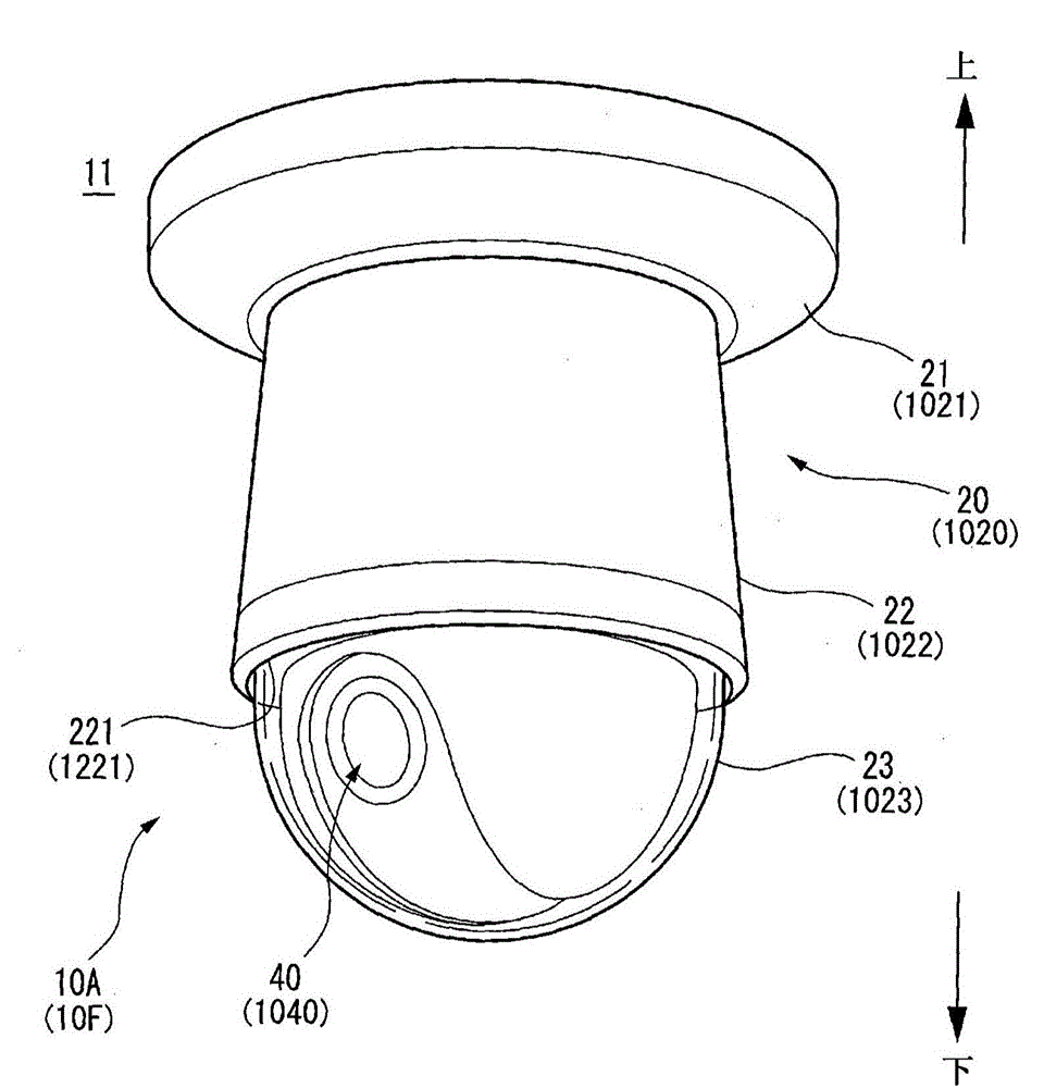
[0091] like figure 1 As shown, the camera device 10A according to the first embodiment is, for example, attached to a ceiling surface 11 as another member attachment surface, and can be used as a surveillance camera that can monitor a lower area 360 degrees from the ceiling surface 11 .
[0092] In the following description, it is considered that the ceiling surface 11 is the upper side, and the opposite side of the ceiling surface 11 is the lower side.
[0093] The camera device 10A has a main body (camera main body) 20 that can be attached to the ceiling surface 11 . The main body 20 has: a disc-shaped base 21 attached to the ceiling surface 11 ; a substantially cylindrical receiving portion 22 attached to the underside of the base 21 and a light-transmitting hemispherical cover 23 that covers the opening 221 of the accommodating portion 22 .
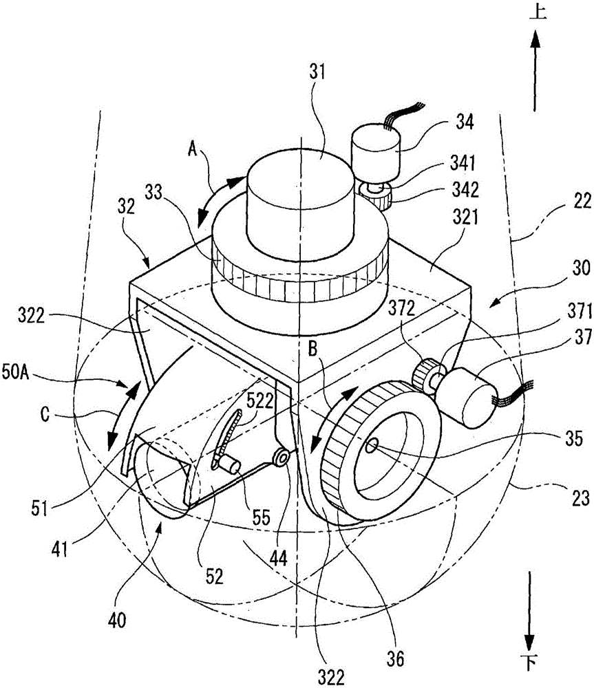
[0094] like figure 2 As shown, the internal mechanism 30 is housed in the main body 20 . The internal mechanism 30 accommodate...
no. 2 example
[0137] Next, the camera device according to the second embodiment will be described.
[0138] The same reference numerals and symbols are applied to the same parts as those of the camera device 10A in the first embodiment, and repeated descriptions will be omitted.
[0139] like Figure 11 As shown, in the camera device 10B in the second embodiment, the light shielding plate portion 50B has a pair of (sub) light shielding plates 571 and 572 (an upper light shielding plate and a lower light shielding plate). The two light shielding plates 571 and 572 are separated from each other by a distance larger than the outer diameter of the lens 41 , and the opening 58 is provided between the two light shielding plates 571 and 572 .
[0140] Therefore, if Figure 12A As shown, in the state where the light-shielding ratio M=0, the entire front portion of the lens 41 is exposed forward from the opening 58 .
[0141] At the same time, the light-shielding plate portion 50B is lowered (at ...
no. 3 example
[0151] Next, the camera device according to the third embodiment will be described.
[0152] In the camera apparatuses 10A and 10B in the first and second embodiments, the visor portions 50A and 50B are moved to partially block the light of the lens 41 to prevent the images from overlapping, thereby obtaining the most appropriate images.
[0153] In the camera device 10C in the third embodiment, the structure of the visor portions 50A and 50B is used to realize the function of protecting privacy.
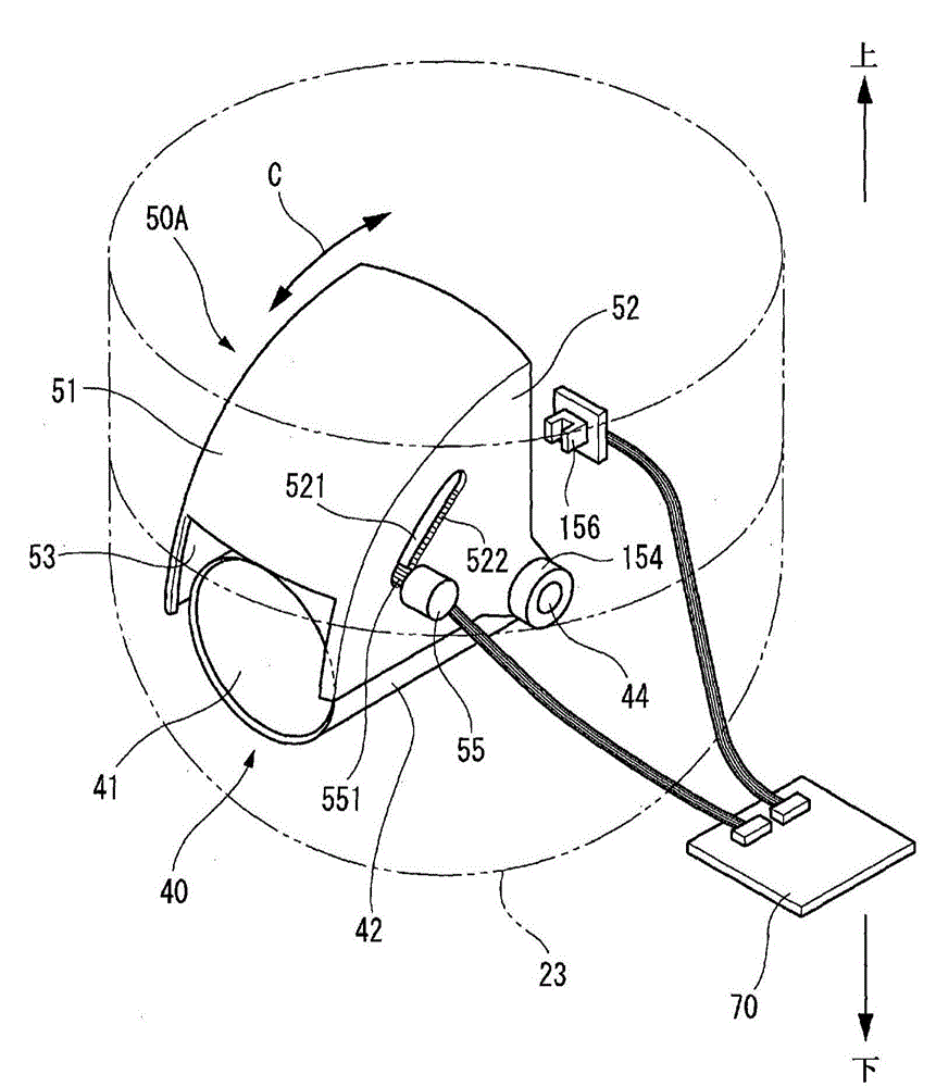
[0154] like Figure 14 As shown, in the camera device 10C of the third embodiment, the third motor 55 is controlled (refer to Figure 3 to Figure 5 ) to move the visor 51 to cover the entire front sphere of the lens 41 to be hidden. In this way, when the light blocking plate 51 is in a position to cover the entire front sphere of the lens 41 to be hidden (light blocking ratio M=100%), the privacy of the person to be imaged projected on the camera unit 40 can be protected, and It ...
PUM
 Abstract
Description
Claims
Application Information