
Endotracheal tube with pharyngeal suction tube

A tracheal tube and suction tube technology, applied in the field of medical equipment, can solve the problems of cumbersome operation, heavy nursing workload, mucosal damage, etc., and achieve the effects of reducing side effects, improving removal efficiency, and moisturizing mucosa

Active Publication Date: 2017-07-28
关开泮
View PDF9 Cites 0 Cited by
  • Summary
  • Abstract
  • Description
  • Claims
  • Application Information

AI Technical Summary

Problems solved by technology

However, these measures are ineffective and cannot effectively prevent pharyngeal secretions from entering the lungs, resulting in a high incidence of ventilator-associated pneumonia
Suction tubes currently used in clinical practice are likely to cause mucous membrane damage and bleeding, and the cleaning effect is poor
In addition, the existing measures are quite cumbersome to operate, and the nursing workload is heavy

Method used


Image

  • Endotracheal tube with pharyngeal suction tube
  • Endotracheal tube with pharyngeal suction tube
  • Endotracheal tube with pharyngeal suction tube

Examples


Embodiment 1

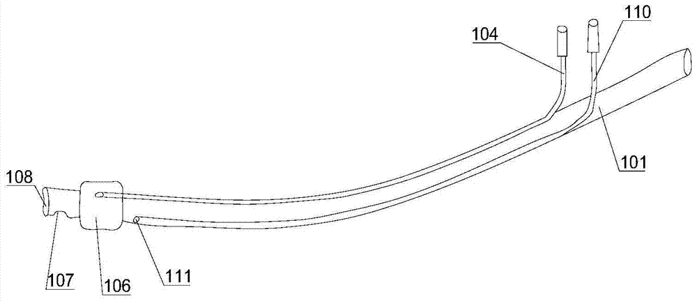
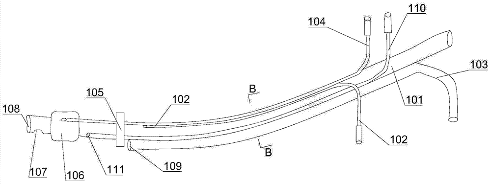
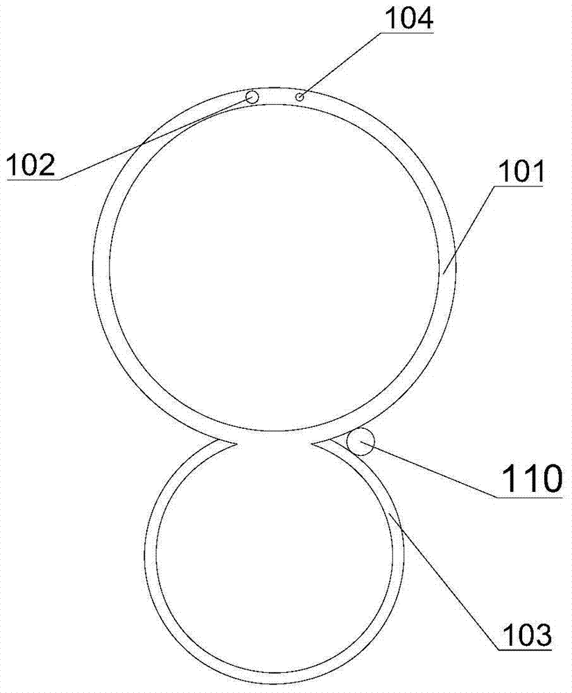
[0040] refer to Figure 1 to Figure 6 , this embodiment provides a tracheal tube with a pharyngeal suction tube 103, the tracheal tube comprises a tracheal tube body 101 and a pharyngeal suction tube 103 for sucking patient's pharyngeal secretions, the tracheal tube body 101 and the pharyngeal suction The tube 103 is integrally formed, and the pharyngeal suction tube 103 is connected to the outer wall of the endotracheal tube body 101 and is fixed directly behind the endotracheal tube body 101 (referring to the patient's supine position, the placement position after the endotracheal tube is successfully inserted and fixed, the head is up, The feet are the bottom, the nose is the front, and the pillow is the back). In this embodiment, the diameter of the pharyngeal suction tube is equivalent to that of the sputum suction tube F16, which is about 5.33 mm.

[0041] The main body of the endotracheal tube is no different from the currently commonly used endotracheal tube, such as ...

Embodiment 2

[0048] refer to Figure 7 to Figure 9 , the main difference between this embodiment and Embodiment 1 is:

[0049] The endotracheal tube with pharyngeal suction tube 103 further includes: a second flushing tube 302 embedded in the front wall of the pharyngeal suction tube 103 connected to the endotracheal tube body 101 . The opening at one end of the second irrigation tube 302 is located in the lumen behind the suction ports 202 on both sides, and is close to the port of the pharyngeal suction tube 103 (ie, the port of the front fold). The second flushing tube 302 is separated from the pharyngeal suction tube 103 after going out 3.0 cm from the incisor line with the pharyngeal suction tube 103, and the extension tube is externally connected with a syringe hub. The second flushing tube 302 can flush the suction port and lumen of the pharyngeal suction tube 103 to keep it unobstructed, and can also flush the patient's pharyngeal floor to keep the pharyngeal floor clean.

[0050...


PUM


Abstract

The invention provides a tracheal catheter with a pharyngeal suction tube, which belongs to the technical field of medical equipment. The endotracheal tube includes an integrally formed endotracheal tube body and a pharyngeal suction tube for sucking patient's pharyngeal secretions, and the pharynx suction tube is fixedly connected with the side wall of the endotracheal tube body. During orotracheal intubation, the pharyngeal suction tube is also introduced while the tracheal tube is inserted. The pharyngeal suction tube can be left in the patient's pharynx for a long time, avoiding the trouble of repeatedly using the sputum suction tube in and out of the pharynx. And cause discomfort or injury to patients, reducing the difficulty of nursing. The endotracheal tube body is equipped with a baffle, the front end of the pharyngeal suction tube is bent, the port is closed, the side suction hole is set, and three irrigation tubes are attached to the tube to improve the removal efficiency of pharyngeal secretions and keep the oropharyngeal mucosa moist and clean , and reduces the side effect of using conventional suction tube suction. In addition, setting the gastric tube through the tunnel makes gastric tube insertion simple and easy.

Description

technical field [0001] The invention relates to the technical field of medical equipment, in particular to an endotracheal tube with a pharyngeal suction tube. Background technique [0002] Endotracheal intubation connected to ventilator-assisted breathing is the main clinical measure used in the treatment of respiratory failure, severe heart failure and surgical anesthesia, but endotracheal intubation often causes ventilator-associated pneumonia, which prolongs the hospital stay, increases costs, and may even lead to an increase in mortality. Ventilator-associated pneumonia is often caused by multi-drug resistant bacteria, which has become a medical problem of the century. There are many causes of ventilator-associated pneumonia after tracheal intubation, among which inhalation of oropharyngeal and nasal secretions is the most important factor. Preventing oropharyngeal and nasal secretions from entering the lungs can significantly reduce the incidence of ventilator-associa...

Claims


Application Information

Patent Timeline
Patent Type & Authority Patents(China)
IPC IPC(8): A61M16/04A61M1/00
CPCA61M16/04A61M16/0434A61M16/0463A61M2205/18A61M16/0475A61M16/0479A61M16/0486A61M16/161A61M16/0488A61M16/0409A61M16/0477
Inventor 关开泮
Owner 关开泮
Learn More