Fluid Dispensing System and Reservoir

A liquid storage and fluid technology, applied in the field of liquid storage, can solve problems such as insufficient supply and fluid supply

Active Publication Date: 2017-10-10
HEISHIN ENGINEERING & EQUIPMENT CO LTD
View PDF7 Cites 0 Cited by
  • Summary
  • Abstract
  • Description
  • Claims
  • Application Information

AI Technical Summary

Problems solved by technology

[0007] When the above-mentioned regulator 210 is provided, when the discharge amount of the discharge device 206 is large, the fluid cannot be supplied from the regulator 210 side to the discharge device 206 in a timely manner at the start of discharge, and the supply may be insufficient.

Method used


Image

  • Fluid Dispensing System and Reservoir
  • Fluid Dispensing System and Reservoir
  • Fluid Dispensing System and Reservoir

Examples


Embodiment Construction

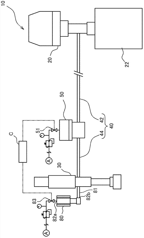
[0052] Hereinafter, a fluid discharge system 10 according to an embodiment of the present invention will be described with reference to the drawings.

[0053] Such as figure 1 As shown, the fluid discharge system 10 is configured to connect the supply device 20 and the discharge device 30 through the supply channel 40 . In addition, the fluid discharge system 10 is configured such that a regulator 50 is provided at an intermediate position of the supply channel 40 and an accumulator 80 is attached to the discharge device 30 . The fluid discharge system 10 is a system for discharging the fluid supplied from the supply device 20 from the discharge device 30 onto a workpiece.

[0054] The supply device 20 is a device for sucking a fluid from a storage portion 22 storing the fluid and feeding the fluid under pressure. The supply device 20 is connected to the supply channel 40 through a pipe. Therefore, the fluid sucked from the reservoir by the supply device 20 can be pressuri...


PUM


Abstract

It is an object of the present invention to provide a fluid discharge system and a liquid accumulator, the fluid discharge system is provided with a regulator having a pressure regulating function and a shut-off function at the middle position of the supply channel, and the fluid discharge system can be used even when the discharge amount is large, etc. It is also possible to prevent insufficient fluid supplied to the discharge device; the fluid discharge system (10) is provided with: a supply device (20), a discharge device (30), a supply channel (40) connecting the supply device (20) and the discharge device (30) , a regulator (50), and a liquid reservoir (80) attached to the discharge device (30); the regulator (50) is arranged in the middle of the supply channel (40) and has a pressure regulating function and a cutting function; The liquid container (80) can store the fluid sucked back by the suck-back action, and supply the stored fluid to the ejection device (30) during the ejection action.

Description

technical field [0001] The present invention relates to a fluid discharge system capable of stably supplying a fluid to a discharge device to exhibit stable discharge performance in the discharge device, and an accumulator applicable to the fluid discharge system and the like. Background technique [0002] Conventionally, a material supply system disclosed in Patent Document 1 below has been proposed as a device for supplying a fluid to a discharge device. The material supply system of Patent Document 1 is configured such that a variable flow control valve, an on-off valve, and an accumulator are provided on a supply line between a pump provided in a fluid supply source and a dispenser provided as a discharge device. . Furthermore, the fluid pressurized and sent by the pump can be supplied to the discharge device, and the fluid can be discharged from the discharge device. [0003] [Prior Art Literature] [0004] 【Patent Literature】 [0005] Patent Document 1: Japanese Ga...

Claims


Application Information

Patent Timeline
Patent Type & Authority Patents(China)
IPC IPC(8): B05C11/10B05C11/11
Inventor 杉野祥弘青田哲典
Owner HEISHIN ENGINEERING & EQUIPMENT CO LTD
Why Eureka
Try Eureka