Elbow injection mold

A technology for injection molds and pipe bends, which is applied in the field of injection mold mechanism design, can solve problems such as difficulty in ensuring the closure and sealing of mold cavities, excessive injection molding burrs, and difficulty in determining gate positions, so as to ensure molding quality, reasonable structural design, and work stable effect

Inactive Publication Date: 2015-11-11
季音
View PDF5 Cites 9 Cited by
  • Summary
  • Abstract
  • Description
  • Claims
  • Application Information

AI Technical Summary

Problems solved by technology

[0002] like figure 1 As shown, when the injection molding of the double-section elbow is limited by the characteristics of the product shape, the existing molds have the following problems in actual production: First, it is difficult to determine the position of the gate, and it is easy to find deviations, resulting in insufficient filling and underfilling of the product during injection molding. Injection and other defects, another problem is that it is difficult to ensure the closure and sealing of the mold cavity, there are more flashes in injection molding, and it is difficult to ensure uniform wall thickness; the third is that the mold is produced in a single cavity mold, and the efficiency is low; therefore, a special demoulding core must be designed. Mechanism and mold structure to complete the automatic injection molding production of products

Method used


Image

  • Elbow injection mold
  • Elbow injection mold
  • Elbow injection mold

Examples


Embodiment Construction

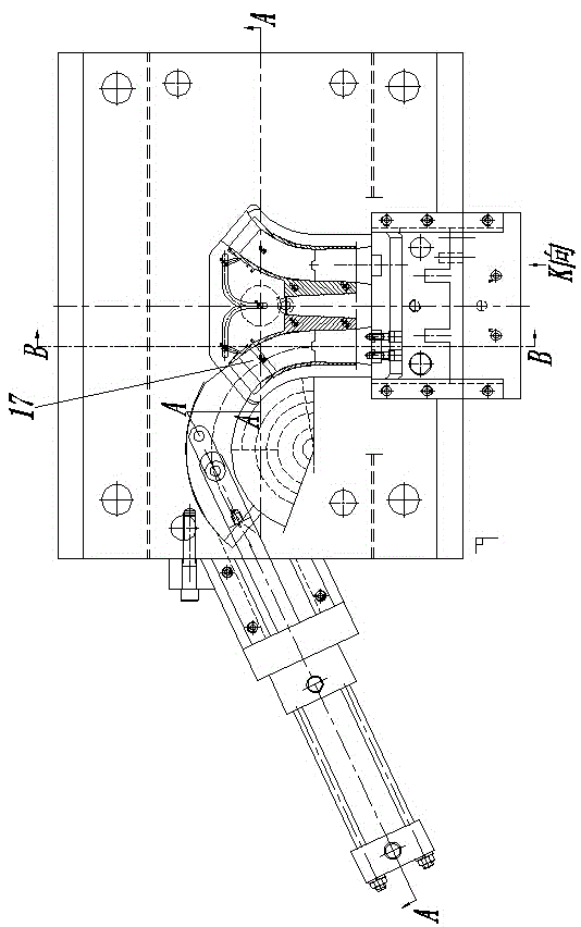
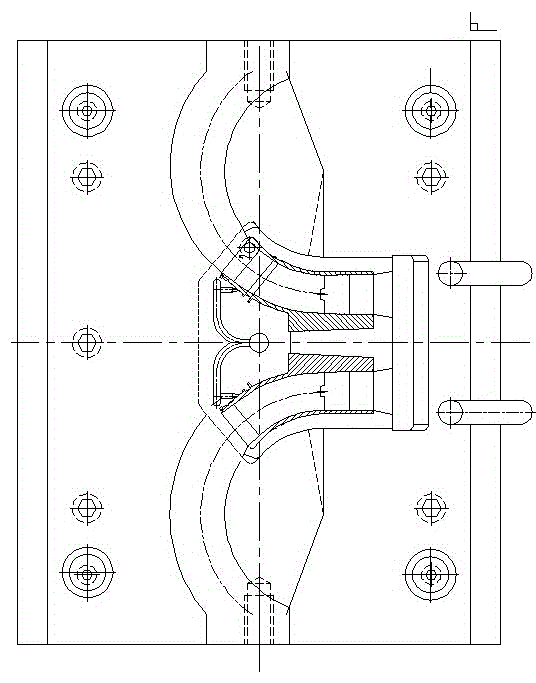
[0018] Figure 1-7 Shown is a related explanatory diagram of the present invention; a curved pipe injection mold, including an upper mold seat plate 1, a cavity fixing plate 2, a core fixing plate 3, a mold foot pad 4, a thimble cover plate 5, and a thimble push plate 6 , Lower mold seat plate 7, core insert 8, cavity insert 9, elbow core-pulling cylinder 10, cylinder pull bar 11, first connecting pin 12, central small pull block 13, second connecting pin 14, circle Arc slider 15, arc guide block 16, bent pipe core 17, straight pipe core 18, slider body 19, oblique guide post 20, slider reinforcing bracket 21, such as figure 2 , Figure 4 , Figure 5 , Figure 6 shown.

[0019] The mold frame structure assembly includes an upper mold seat plate 1, a cavity fixed plate 2, a core fixed plate 3, a mold foot pad 4, a thimble cover plate 5, a thimble push plate 6, and a lower mold seat plate 7, such as Figure 4 shown.

[0020] The mold molding assembly includes a core inser...


PUM


Abstract

The invention provides an elbow injection mold. The elbow injection mold comprises an upper mold base plate, a cavity fixing plate, a core fixing plate, a mold foot cushion block, an ejector pin cover plate, an ejector pin push plate, a lower mold base plate, a core insert, a cavity insert, an elbow core pulling oil cylinder, an oil cylinder stay, a first connecting pin, a small center pull block, a second connecting pin, an arc-shaped sliding block, an arc-shaped guiding block, an elbow core, a straight tube core, a sliding block body, an oblique guide pillar and a sliding block reinforcing support. By the adoption of the elbow injection mold, the defects of the prior art that in the two-section elbow injection molding process, filling is insufficient and short shot is caused are overcome, and the practical production problems that mold cavity pressure is hard to balance, the number of burrs is large, filling is insufficient, wall thickness uniformity is hard to guarantee, and efficiency is low are solved; automatic zero-defect molding is achieved with the simple mechanism, and product molding quality is effectively guaranteed; the structural design is reasonable, the structure is compact, and working is stable.

Description

technical field [0001] The invention relates to the field of injection mold mechanism design, in particular to an injection mold for bent pipes. Background technique [0002] Such as figure 1 As shown, the injection molding of the double-section elbow is limited by the characteristics of the product shape. The existing mold has the following problems in actual production: First, it is difficult to determine the position of the gate, and it is easy to find deviations, resulting in insufficient filling and underfilling of the product during injection molding. Injection and other defects, another problem is that it is difficult to ensure the closure and sealing of the mold cavity, there are many injection molding flashes, and it is difficult to ensure uniform wall thickness; the third is that the mold is produced in a single cavity mold, and the efficiency is low; therefore, a special demoulding core must be designed. Mechanism and mold structure to complete the automatic inje...

Claims


Application Information

Patent Timeline
Patent Type & Authority Applications(China)
IPC IPC(8): B29C45/26B29C45/33B29C45/32B29C45/27
CPCB29C45/0025B29C45/2602B29C45/261B29C45/27B29C45/32B29C45/33B29C45/332
Inventor 季音
Owner 季音
Why Eureka
Try Eureka