Moulding body and method for production thereof

A body, molding material technology, applied in the direction of processing and manufacturing, manufacturing tools, additive manufacturing, etc., can solve problems such as high investment

Active Publication Date: 2015-11-11
LEONHARD KURZ STIFTUNG & CO KG
View PDF5 Cites 6 Cited by
  • Summary
  • Abstract
  • Description
  • Claims
  • Application Information

AI Technical Summary

Problems solved by technology

[0005] In addition, producing and operating complex molds are necessary tools in injection molding
This requires high investment and having variations or diversification of manufactured components is a problem
In addition, molds must be replaced regularly due to the high level of wear due to the high pressure and high temperatures mentioned above

Method used


Image

  • Moulding body and method for production thereof
  • Moulding body and method for production thereof
  • Moulding body and method for production thereof

Examples


Embodiment Construction

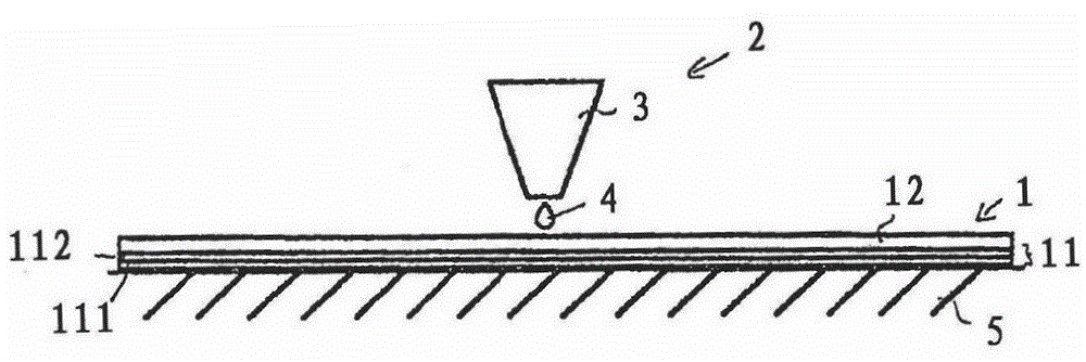
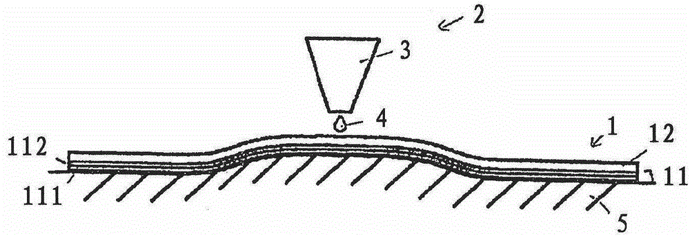
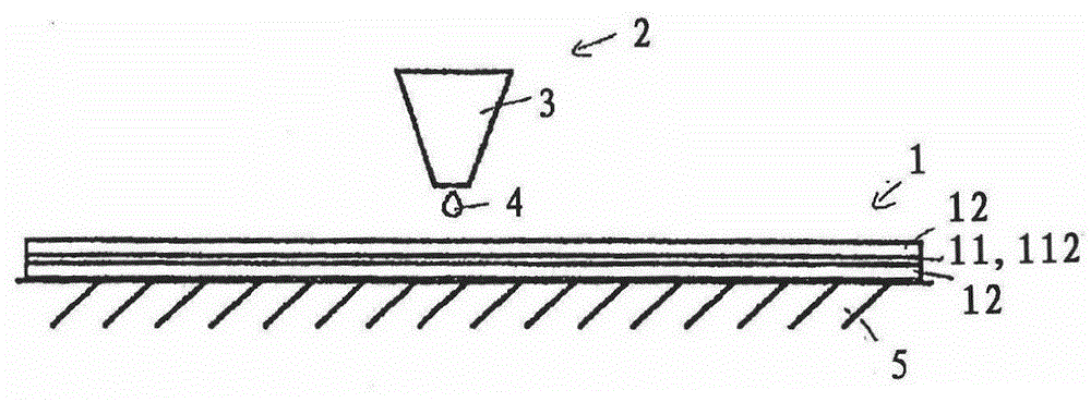
[0073] The molded body 1 comprises a foil layer 11 to which a plastic molding material 12 is applied by means of three-dimensional printing.

[0074] In this example, the foil layer 11 may be a laminate foil or a transfer foil. In the latter case, the foil layer 11 comprises a carrier layer 111 to which is adhered a transfer layer 112 which ultimately remains in the molded body, so that it is detachable.

[0075] The layer thickness of the foil layer 11 is preferably 10 μm to 250 μm, more preferably 20 μm to 250 μm.

[0076] The foil layer 11 may have an adhesion promoting layer, which is not represented in the figures. Plastic molding material 12 is applied to this adhesion promoting layer. In this example, it could be a plastic and / or a heat-activated adhesive chemically related to the plastic molding material, for example, a polyvinyl chloride (PVC)-based or acrylic-based adhesive, or a PVC- and acrylic-based adhesive mixture of adhesives.

[0077] Furthermore, the foil...


PUM

PropertyMeasurementUnit
thicknessaaaaaaaaaa
thicknessaaaaaaaaaa

Abstract

The invention relates to a method for producing a molded body (1) having the following steps: a) providing a foil ply (11); b) applying a plastic molding compound (12) in a predefined three-dimensional shape onto the foil ply (11) by means of a three-dimensional printing method. The invention furthermore relates to a molded body (1) produced in this manner.

Description

technical field [0001] The invention relates to a method of manufacturing a molded body and a molded body manufactured using this method. Background technique [0002] In order to combine decorative and functional elements with plastic parts, it is known to accommodate adjustment foils with such elements in injection molded parts. In this case, the foil layer is located in the injection mold and fixed therein. Subsequently, the plastic molding material is injected into the injection mold where it bonds to the foil layers and cures. A known method of achieving this is the method known as in-mold decoration (IMD) or insert molding. [0003] However, these manufacturing methods are limited in several respects. Due to the high temperatures and pressures involved in injection molding, the choice of foil layers that can be used is firstly limited. In particular metal foils with sensitive electronic functional layers or security elements cannot be used, since they would be dest...

Claims


Application Information

Patent Timeline
Patent Type & Authority Applications(China)
IPC IPC(8): B29C67/00B33Y10/00
CPCB29C65/48B29C67/0055B29C67/0059B29C67/0092B33Y10/00B33Y30/00B33Y40/00B33Y80/00Y10T428/24612Y10T428/24802Y10T428/24901Y10T428/264Y10T428/31507Y10T428/31696Y10T428/31895Y10T428/31931Y10T442/20B29C64/112B29C64/40B29C2795/00B29C64/106B29C64/147B29C64/165B33Y40/20B05D2507/005B05D2203/20B05D1/02B05D2201/02B05D3/002B05D7/14B05D1/26B05D2202/00B05D2502/005B05D2203/24B29C37/0025B29C65/4815B29C66/712B29C66/02B29C66/70B29C66/72327B29C66/742B29C66/41B29C66/7232B29C66/7487B29C66/7484B32B9/042B32B15/10B32B9/041B32B7/12B32B15/082B32B15/04B32B15/00B32B15/085B32B15/08B32B9/045B33Y99/00B32B2255/26B32B2255/08B32B2255/10B32B2255/28B32B2255/06B44C3/02B29C64/393
Inventor K·普福尔特M·哈恩
Owner LEONHARD KURZ STIFTUNG & CO KG
Why Eureka
Try Eureka