Wood fibre based panel with a surface layer

a technology of wood fibre based building panels and surface layers, which is applied in the direction of bandages, manufacturing tools, other domestic articles, etc., can solve the problems of low surface properties, low cost, and low impact resistance of wood veneer, and achieve better surface properties and/or cost structures, attractive surface designs

Active Publication Date: 2015-07-16
VÄLINGE INNOVATION AB
View PDF15 Cites 55 Cited by
  • Summary
  • Abstract
  • Description
  • Claims
  • Application Information

AI Technical Summary

Benefits of technology

[0013]The objective of at least certain embodiments of the disclosure is to provide a building panel, such as a floor panel, with a wood based surface layer, which has a more attractive surface design and / or better surface properties and / or cost structure than present known floorings.
[0026]The embossed portions may be naturally occurring after pressing. For wood veneers having a porous structure, such as hard wood (e.g., angiosperm), porous portions of the veneer form embossed portions after pressing, since these portions do not spring back from their compressed state when the pressure is released. These porous portions are filled with the binder of the sub-layer during pressing. Then the binder cures and / or hardens, the binder locks the position of the porous portions in the compressed state.
[0050]The method preferably comprises the step of applying a foaming agent. The foaming agent may facilitate the displacement of the wood fibre powder and the agent into the holes.

Problems solved by technology

The disadvantage is that a wood veneer generally has a lower impact resistance than laminate floors and the production cost is high when high quality veneers may be used
This will not solve the cost problems.
Material from the sub-layer may fill holes, such as cracks, of the veneer.
The high-density portions do not absorb enough binder from the sub-layer to be locked by the hardened binder after pressing.

Method used


Image

  • Wood fibre based panel with a surface layer
  • Wood fibre based panel with a surface layer
  • Wood fibre based panel with a surface layer

Examples


Embodiment Construction

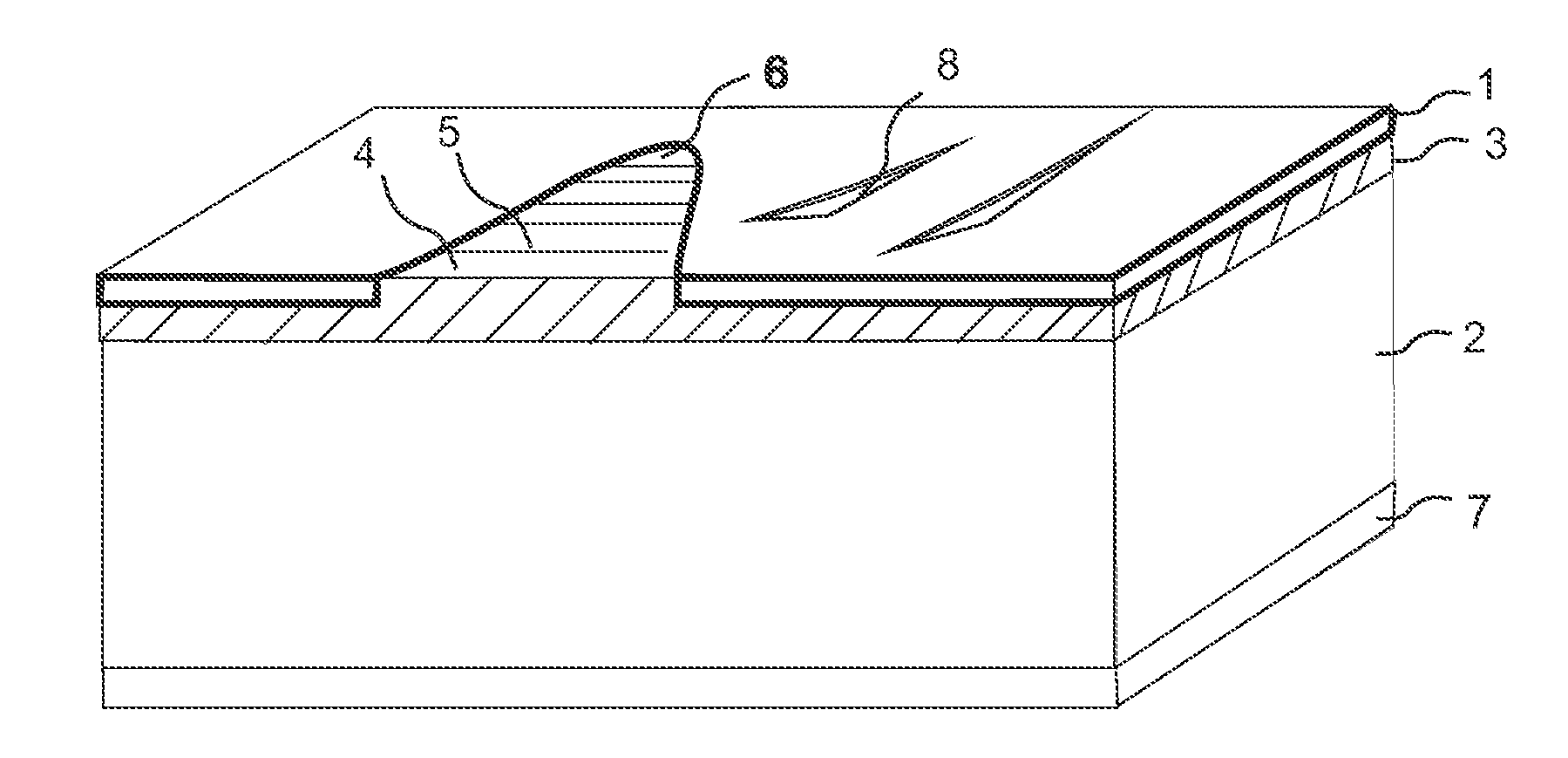
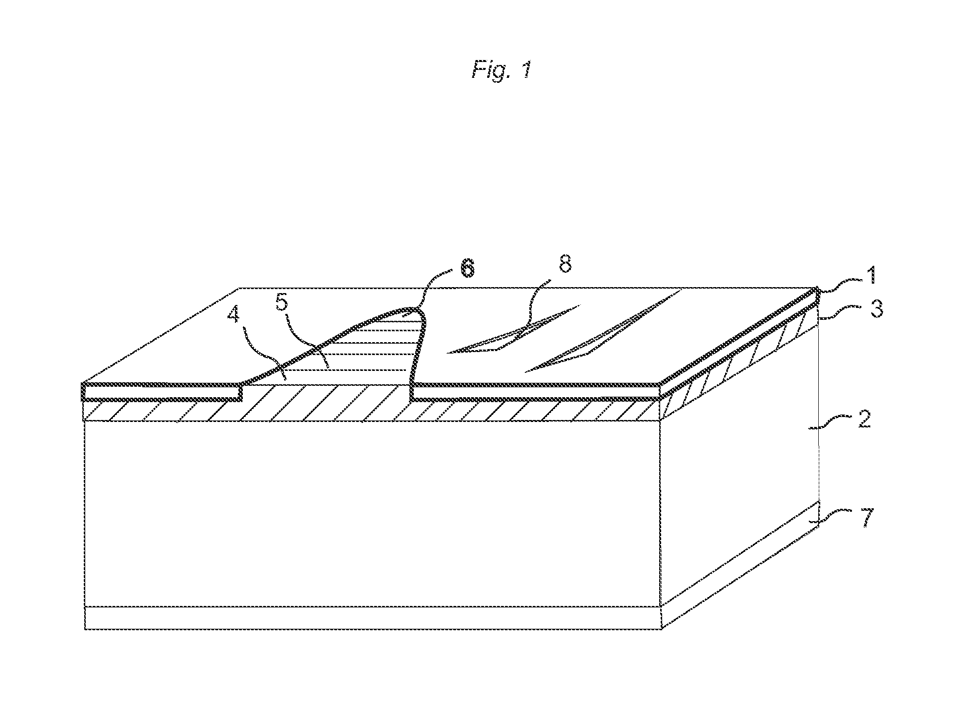
[0062]FIG. 1 shows a building panel with a surface layer 1 comprising a wood veneer, a core 2, and a sub-layer 3 arranged between the surface layer 1 and the core 2. The core 2 may be wood fibre based board such as MDF, HDF, particle board, plywood, OSB etc. The core 2 may be a WPC (Wood Plastic Composite). The core 2 may in one embodiment be a mineral board. The building panel may be a floor panel, a wall panel, a ceiling panel, a furniture component, skirting boards, mouldings, edging profiles, etc.

[0063]A low quality wood veneer is used as a surface layer 1. The veneer comprises cracks and other similar defects. The veneer is pressed against the core 2 with a powder based sub-layer 3 comprising wood fibres 4 and a binder 5 such that the powder floats and fills the cracks. The panel comprises after pressing a surface layer 1 with surface portions 6 comprising material from the sub-layer 3. The surface portions 6 comprising material from the sub-layer 3 extend into the wood veneer....


PUM

PropertyMeasurementUnit
thickaaaaaaaaaa
thickaaaaaaaaaa
thickaaaaaaaaaa

Abstract

A building panel with a surface layer (1) including a wood veneer, a wood fibre based core (2) and a sub-layer (3) between the surface layer (1) and the core (2). The sub-layer (3) includes wood fibres (4) and a binder (5). The surface layer (1) has surface portions (6) including material from the sub-layer (3). The surface portions (6) including material from the sub-layer (3) extend into the wood veneer.

Description

CROSS REFERENCE TO RELATED APPLICATIONS[0001]The present application claims the benefit of Swedish Application No. 1450023-5, filed on Jan. 10, 2014, the benefit of Swedish Application No. 1450552-3, filed on May 12, 2014, and the benefit of Swedish Application No. 1451154-7, filed on Sep. 29, 2014. The entire contents of each of Swedish Application No. 1450023-5, Swedish Application No. 1450552-3, and Swedish Application No. 1451154-7 are hereby incorporated herein by reference in their entirety.TECHNICAL FIELD[0002]The disclosure generally relates but is not limited to the field of wood fibre based building panels with a surface layer, preferably floor panels, wall panels and furniture components.TECHNICAL BACKGROUND[0003]Embodiments of the disclosure are particularly suitable for use in floating floors, which are formed of floor panels with a wood fibre core and a decorative wear resistant surface. The following description of known technique, problems of known systems and object...

Claims


Application Information

Patent Timeline
Patent Type & Authority Applications(United States)
IPC IPC(8): E04F15/04B27N3/02B27N3/08B27N3/00
CPCE04F15/042B27N3/08B27N3/02B27N3/005B27G1/00B27N3/04B27N7/005B32B3/30B32B5/142B32B21/02B32B21/08B32B21/14B32B27/20B32B27/42B32B37/10B32B37/1284B32B37/18B32B38/06B32B2262/067B32B2264/062B32B2266/0214B32B2266/0285B32B2266/14B32B2305/073B32B2307/4026B32B2307/554B32B2317/02B32B2317/16B32B2471/00B32B2607/00B44C1/24B44C5/043B44C5/0438E04F15/045E04F15/082E04F15/085Y10T156/10Y10T156/1039Y10T428/24132Y10T428/24298Y10T428/24314Y10T428/24322Y10T428/24331Y10T428/24339Y10T428/24521Y10T428/24603Y10T428/24612Y10T428/24802Y10T428/24893Y10T428/24992Y10T428/249925Y10T428/24994Y10T428/24995Y10T428/249959Y10T428/249982Y10T428/249985Y10T428/249986Y10T428/249987Y10T428/25Y10T428/253Y10T428/256Y10T428/257Y10T428/3167Y10T428/31862Y10T428/31866Y10T428/31957Y10T428/31989
Inventor PERVAN, DARKOZIEGLER, GORAN
Owner VÄLINGE INNOVATION AB
Why Eureka
Try Eureka