A fully hydraulic amphibious amusement tank hydraulic drive control system

An amphibious, drive control technology, applied in the direction of fluid pressure actuators, servo motors, servo motor components, etc., can solve the problems of not being able to really experience riding in tanks, high cost, rail-type trains that can only be ridden and cannot be operated by hand

Active Publication Date: 2017-01-25
ZONI GREAT HYDRAULIC
View PDF6 Cites 2 Cited by
  • Summary
  • Abstract
  • Description
  • Claims
  • Application Information

AI Technical Summary

Problems solved by technology

The existing amusement tank is a new type of modern amusement vehicle. Common amusement vehicles are wheeled and track-type. Wheeled bumper cars can only be equipped with aerial grids and substations after laying metal plates on limited venues. It can only be used in a room, so its cost is high, and its application range is small. The rail-type train can only be used and cannot be operated by hand, and these cannot really experience the feeling of riding a tank.

Method used


Image

  • A fully hydraulic amphibious amusement tank hydraulic drive control system

Examples


Embodiment Construction

[0022] Below in conjunction with specific embodiment, further illustrate the present invention. It should be understood that these examples are only used to illustrate the present invention and are not intended to limit the scope of the present invention. In addition, it should be understood that after reading the teachings of the present invention, those skilled in the art can make various changes or modifications to the present invention, and these equivalent forms also fall within the scope defined by the appended claims of the present application.

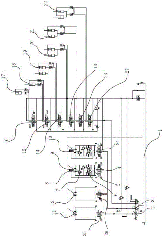
[0023] Such as figure 1 As shown, the embodiment of the present invention relates to a hydraulic drive control system of a fully hydraulic amphibious amusement tank, including a hydraulic oil tank 1 and a hydraulic pump 2, and the hydraulic system also includes a left water spray motor 11 and a right water spray motor 12, the described The hydraulic pump 2 is connected to the P port of the M-type two-position four-way solenoi...


PUM


Abstract

The invention relates to a hydraulic drive control system of a full-hydraulic amphibious amusement tank. The system comprises a hydraulic oil tank and a hydraulic pump. The hydraulic system further comprises a left water spraying motor and a right water spraying motor. The hydraulic pump is connected with a P port of an M-type two-position four-way electromagnetic valve I and a P port of an M-type two-position four-way electromagnetic valve II. The M-type two-position four-way electromagnetic valve I and the M-type two-position four-way electromagnetic valve II are connected with the left water spraying motor and the right water spraying motor through an A port of the M-type two-position four-way electromagnetic valve I and a B port of the M-type two-position four-way electromagnetic valve II respectively. A T port of the M-type two-position four-way electromagnetic valve I and a T port of the M-type two-position four-way electromagnetic valve II are connected with a P port of an H-type three-position four-way electromagnetic valve I and a P port of an H-type three-position four-way electromagnetic valve II respectively. The H-type three-position four-way electromagnetic valve I and the H-type three-position four-way electromagnetic valve II are connected with a left running motor and a right running motor through an A port of the H-type three-position four-way electromagnetic valve I and a B port of the H-type three-position four-way electromagnetic valve II respectively. A power system is shared in the hydraulic drive control system, stepless speed regulation and independent control over aquatic driving and land driving can be achieved, and the hydraulic drive control system is easy to operate, reliable and low in energy consumption.

Description

technical field [0001] The invention relates to the field of hydraulic control systems for amusement equipment, in particular to a hydraulic drive control system for an all-hydraulic amphibious amusement tank. Background technique [0002] Manipulating or experiencing tank driving is a dream of tourists and players. However, the operating cost and maintenance requirements of military tanks, as well as the national military product control, are extremely unlikely to be realized in the playground. The existing amusement tank is a new type of modern amusement vehicle. Common amusement vehicles are wheeled and track-type. Wheeled bumper cars can only be equipped with aerial power grids and substations after laying metal plates on limited venues. Only a room can be used, so its cost is high, its application range is small, rail trains can only be used and cannot be manipulated by hand, and these can not really experience the feeling of riding a tank. [0003] And now many amusem...

Claims


Application Information

Patent Timeline
Patent Type & Authority Patents(China)
IPC IPC(8): F15B11/00F15B13/02
CPCF15B11/00F15B13/02
Inventor 邓开忠
Owner ZONI GREAT HYDRAULIC
Why Eureka
Try Eureka