Piston self-operated regulating valve

A self-operated regulating valve and piston technology, applied in the field of regulating valves, can solve the problems of damaged diaphragm, self-operated regulating valve flow regulation failure, limited deformation of the diaphragm, etc., and achieve the effect of long stroke and automatic flow adjustment

Inactive Publication Date: 2015-11-11
CHONGQING BRIGHTY INSTR
View PDF0 Cites 4 Cited by
  • Summary
  • Abstract
  • Description
  • Claims
  • Application Information

AI Technical Summary

Problems solved by technology

The disadvantage of the above scheme is that the existing feedback mechanism includes a casing, and the diaphragm in the casing divides the inner cavity of the casing into an upper chamber and a lower chamber, and a moving plate connected to the execution structure is slidably fitted in the lower chamber, and the diaphragm and the A return spring is set between the moving plates, and the upper chamber communicates with the co

Method used


Image

  • Piston self-operated regulating valve

Examples


Embodiment Construction

[0012] The present invention will be described in further detail below by means of specific embodiments:

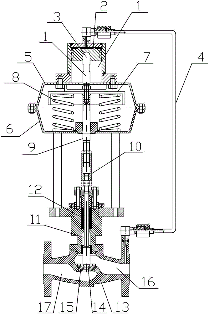
[0013] The reference signs in the drawings of the description include: piston cavity 1, piston 2, connecting piece 3, control pipeline 4, upper cover 5, lower cover 6, pressure plate 7, return spring 8, actuator rod 9, sleeve 10, valve Rod 11, sealing stuffing box 12, valve body 13, valve core 14, valve seat 15, water inlet chamber 16, water outlet chamber 17.

[0014] Embodiment The piston self-operated regulating valve is basically as attached figure 1 Shown:

[0015] The piston self-operated regulating valve is divided into three parts: the feedback mechanism, the actuator, and the valve body 13 from top to bottom.

[0016] The valve body 13 is provided with a water inlet chamber 16 and a water outlet chamber 17, and the water inlet chamber 16 and the water outlet chamber 17 are connected through the valve port, and the water flows from the clean water chamber to the...


PUM


Abstract

The invention belongs to the technical field of regulating valves, and relates to a piston self-operated regulating valve. The piston self-operated regulating valve sequentially comprises three parts including a feedback mechanism, an actuating mechanism and a valve body from top to bottom. A valve element is arranged on a valve port of the valve body in a matched manner. The valve element is driven by a valve rod to open and close the valve port. The actuating mechanism comprises an upper cover and a lower cover. The upper cover and the lower cover are oppositely combined to form an installation cavity. The installation cavity is internally provided with a pressing plate and an actuating rod connected with the pressing plate. The actuating rod is fixedly connected with the valve rod through a sleeve. Return springs are arranged between the pressing plate and the lower cover. The feedback mechanism comprises a control pipeline and a piston cavity. The piston cavity is divided into an upper cavity body and a lower cavity body through a piston. The lower end of the control pipeline is communicated with a water inlet cavity in the valve body, and the upper end of the control pipeline is connected with the upper cavity body. The bottom of the piston is fixedly provided with a connecting piece in an interference manner. The connecting piece is fixedly connected with the actuating rod. Compared with a traditional membrane deformed within the short stroke, through the cooperation between the piston and the piston cavity, the piston stroke is determined by the length of the piston cavity, the stroke is longer, larger pressure can be borne, and the flow can be automatically adjusted when the pressure of a medium inside the valve body is higher.

Description

technical field [0001] The invention belongs to the technical field of regulating valves. Background technique [0002] The self-operated valve relies on the self-pressure of the medium flowing through it as the energy to drive the valve to work automatically, without external power supply and secondary instruments. Self-operated regulating valves use the feedback signal (pressure, pressure difference, temperature) at the output end of the valve to transmit to the actuator through the signal tube to drive the disc to change the opening of the valve to achieve the purpose of adjusting pressure, flow and temperature. [0003] Since the existing self-operated regulating valve structure includes a valve body, a valve core, an adjusting rod, an actuator, a feedback mechanism, and a control pipeline, wherein a valve channel is opened in the valve body, and the valve core is installed in the valve port of the valve channel. When moving, the valve port is opened or closed. The move...

Claims


Application Information

Patent Timeline
IPC IPC(8): F16K17/30F16K31/122
CPCF16K17/30F16K31/1221F16K31/1223
Inventor 王军
Owner CHONGQING BRIGHTY INSTR
Why Eureka
Try Eureka