
Method for carrying out object deformation phase measurement by using optical flow field

A technology of phase measurement and optical flow field, which is applied in measurement devices, optical devices, instruments, etc., to achieve the effect of overcoming large demodulation errors and simple process

Inactive Publication Date: 2015-11-11
SHANDONG NORMAL UNIV
View PDF4 Cites 11 Cited by
  • Summary
  • Abstract
  • Description
  • Claims
  • Application Information

AI Technical Summary

Problems solved by technology

[0004] The object of the present invention is to solve the above problems, and provide a method for measuring the deformation phase of an object by using the optical flow field. Only two fringe images in the spatial domain can be used to complete the extraction of the deformation phase without converting to the frequency domain and Phase unwrapping operation, suitable for dynamic measurement, and the effect of extracting phase is better in the denser fringe area, which completely overcomes the disadvantage of large demodulation error when the fringe is too dense in the existing phase demodulation method

Method used


Image

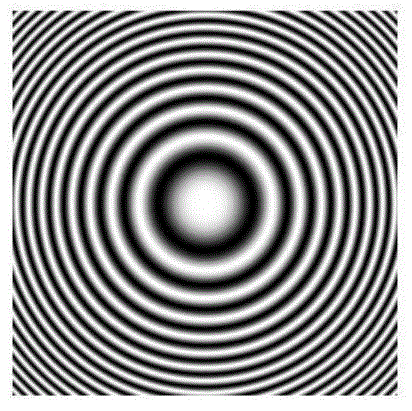
  • Method for carrying out object deformation phase measurement by using optical flow field
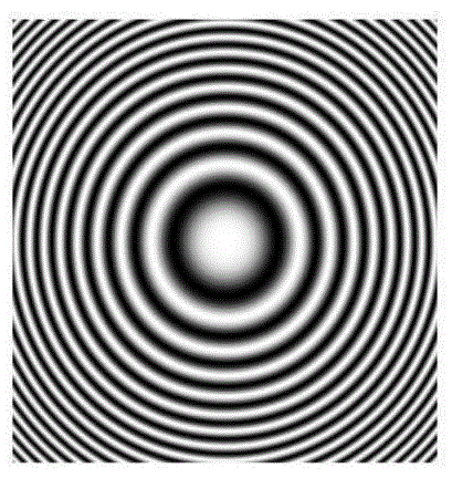
  • Method for carrying out object deformation phase measurement by using optical flow field
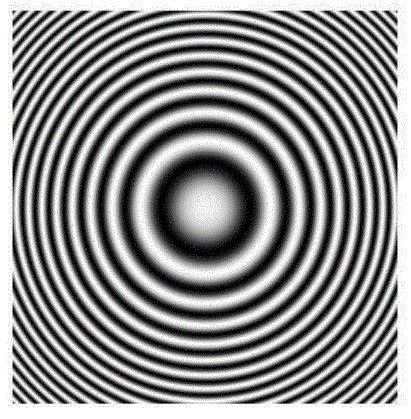
  • Method for carrying out object deformation phase measurement by using optical flow field

Examples


Embodiment Construction

[0025] The present invention will be further described below in conjunction with the accompanying drawings and embodiments.

[0026] The method for measuring the deformation phase of an object by using an optical flow field comprises the following steps:

[0027] Step 1: According to the basic assumption of the optical flow field theory, two components u and v of the motion vector between two consecutive images are obtained;

[0028] Step 2: Extract the horizontal frequency f of the first frame image stripes by the window Fourier transform method x0 and longitudinal frequency f y0 ;

[0029] Step 3: Using the two components u and v of the motion vector obtained in the step 1 and the step 2 to obtain the horizontal frequency f of the stripes x0 and longitudinal frequency f y0 Calculate the amount of change in phase.

[0030] 1 Calculation of motion vector

[0031] Assuming that the gray value of the pixel point (x, y) at time t is I(x, y, t), the point moves to a new posi...


PUM


Abstract

The present invention discloses a method for carrying out object deformation phase measurement by using an optical flow field. The method comprises the steps of (1) according to the basic assumption of the optical flow field theory, obtaining the two components u and v of a motion vector between two frames of successive images, (2) extracting the horizontal frequency fx0 and the vertical frequency fy0 of a first frame image fringe by a window Fourier transform method, and (3) using the two components u and v of the motion vector obtained in the step (1) and the horizontal frequency fx0 and the vertical frequency fy0 to calculate to obtain the change amount of a phase. According to the method, only two fringe images are used in a space domain to complete the extraction of the deformation phase, the operations of switching to a frequency domain and a phase unwrapping are not needed, the method is suitable for dynamic measurement, the effect of phase extraction is better in an area with intensive fringes, the disadvantage of large demodulation error when fringes are too dense in a present phase demodulation method, the process is simple and convenient, and the a new way is provided for optical interference dynamic measurement by the method.

Description

technical field [0001] The invention relates to a method for measuring the deformation phase of an object by using an optical flow field. Background technique [0002] Due to its unique advantages, optical interferometry plays a very important role in the measurement of three-dimensional shape and deformation of objects, such as electronic speckle interferometry, holographic interferometry, and moiré interferometry. In these methods, it is necessary to demodulate the phase information of each point in the fringe pattern to realize deformation measurement. The methods of demodulating the phase are mainly divided into two categories: time phase measurement method and space phase measurement method. Time-phase measurement methods, such as Temporal Phase-shifting Method (TPM), etc., have the advantages of high displacement measurement accuracy and simple structure, but this type of method requires more fringe patterns and takes a long time. Only applicable to static measuremen...

Claims


Application Information

Patent Timeline
Patent Type & Authority Applications(China)
IPC IPC(8): G01B11/16
Inventor 高延红赵冉孙平
Owner SHANDONG NORMAL UNIV
Learn More