
Directional modulation signal design method based on spatial Fourier transformation

A Fourier transform and directional modulation technology, applied in the directions of space transmit diversity, modulated carrier system, transmission system, etc., can solve the problems of reducing algorithm complexity, relative phase relationship distortion, inability to demodulate communication information, etc., to achieve design The method is simple and intuitive, the degree of distortion is guaranteed, and the effect is easy to achieve in engineering

Active Publication Date: 2015-11-11
NANJING UNIV OF POSTS & TELECOMM
View PDF4 Cites 5 Cited by
  • Summary
  • Abstract
  • Description
  • Claims
  • Application Information

AI Technical Summary

Benefits of technology

This patented technology describes an improved way to improve directional radio frequency (RF) transmission by creating waveforms from two or three dimensional antenna elements arranged at specific angles. These wavesformations help reduce interference caused when transmitting electromagnetic radiation wirelessly without affecting other devices nearby. By adjusting these parameters during wireless communications, it becomes possible to achieve better performance compared to previous methods such as time division multiple access (TDMA).

Problems solved by technology

This patented technical problem addressed in the patents relates to improving the security level of communicating data during wirelessly transferring over long distances due to various factors like interference sources and potential attacks against devices called quantum computers. Current methods have limitations when applied to complex encryption techniques involving large numbers of bits per second. Therefore there exists a challenge towards developing a stronger authenticated cryptographic key agreement mechanism for reliable communication within limited spaces where many people may want access simultaneously.

Method used


Image

  • Directional modulation signal design method based on spatial Fourier transformation
  • Directional modulation signal design method based on spatial Fourier transformation
  • Directional modulation signal design method based on spatial Fourier transformation

Examples


Embodiment 1

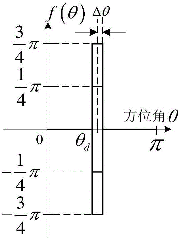
[0086] Single user channel with pencil phase beam:

[0087] Let the azimuth θ where the desired receiver is located d =70°, Δθ=6°, the number of elements of the phased array is 13 and the expected digital modulation signal is a QPSK modulation signal. From formulas (5) and (7), we can get the excitation w of the array element k ,k=-N,...,0,...N. Figure 3(a) and 3(b) The comparison diagrams of the relative amplitude and phase of different modulation symbols transmitted by the pencil-shaped phase beam direction modulation signal transmitter and the array element weighted signal of the traditional transmitter are given. Figure 4(a)(c)(c) and Figure 5(a)(b) respectively show the radiation signal pattern function of the pencil-shaped phase beam direction modulation signal transmitter and the traditional transmitter and the constellation diagram of the received signal in different azimuths. It can be seen from the figure that the pencil-shaped phase beam direction modulation si...

Embodiment 2

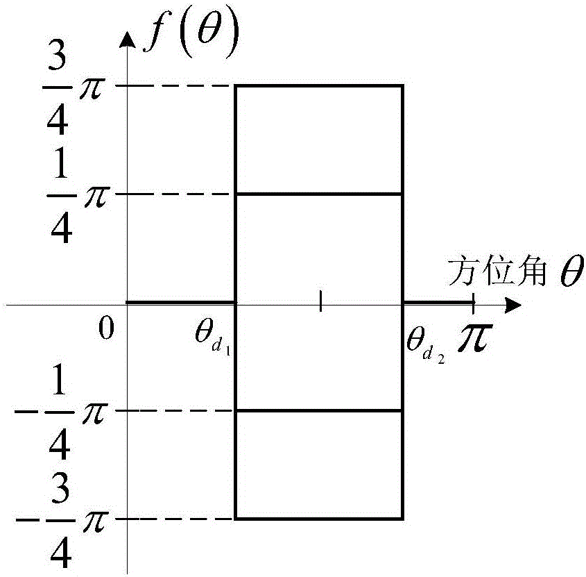
[0090] Broadcast channel for fanned phase beams:

[0091] Let the azimuth range expected to be covered be The number of phased array transmitting elements is 31 and the expected digital modulation signal is QPSK modulation signal. From formulas (5) and (7), we can get the excitation w of the array element k ,k=-N,...,0,...N. Figure 7(a) and 7(b) The comparison diagrams of the relative amplitude and phase of different modulation symbols transmitted by the pencil-shaped phase beam direction modulation signal transmitter and the array element weighted signal of the traditional transmitter are given. Figure 8(a)(b)(c) and Figure 9(a)(b) respectively show the radiation signal pattern function of the fan-shaped phase beam direction modulation signal transmitter and the constellation diagram of the received signal in different azimuths. It can be seen from the figure that the fan-shaped phase beam direction modulation signal transmitter is compared with the traditional transmit...

Embodiment 3

[0094] Multi-user channel with quadrature phase beams:

[0095] Assuming that there are two expected users in the system, the locations are respectively In the algorithm simulation, Δθ=6°, the number of phased array elements is 13 and the expected digital modulation signal is QPSK modulation signal. Since the two users transmit information codes differently, the expected phase function f(θ) has 16 different phase function forms. Next, we use user 1 to send QPSK modulation symbol '11' and user 2 to send QPSK modulation symbol '11' respectively, The phase functions of the four combinations of '1-1', '-11', and '-1-1' are taken as examples to illustrate the design method of the direction modulation signal in this paper. From formulas (5) and (7), we can get the excitation w of the array element k ,k=-N,...,0,...N. Figure 11(a) and (b) show the comparison diagrams of the relative amplitude and phase of different modulation symbols transmitted by the pencil-shaped phase beam di...


PUM


Abstract

The invention provides a directional modulation signal design method based on spatial Fourier transformation. The method comprises the following steps of establishing desired phase wave beam spatial coverage functions in ideal conditions relative to different communication models; and acquiring a phased array element weighted value according to the spatial Fourier transformation pair relation among phase wave beams and the array element weighted value of a phased array in a directional modulation signal transmitter to achieve a directional modulation signal design in different communication models. By using the directional modulation signals designed by the method, valid users can normally demodulate received directional modulation signals through common digital signal receivers. As to wiretappers in undesirable directions, their wiretapping receivers cannot demodulate useful communication information from received signals due to the relative phase relationship distortion of constellation points in a received signal constellation diagram. The invention provides a safe transmission method for transmitting communication information in wireless channels.

Description


Claims


Application Information

Patent Timeline
Owner NANJING UNIV OF POSTS & TELECOMM
Learn More