A New Type of Stamping Flip Chip V-Curved Die

A new type of flip-chip technology, applied in the direction of forming tools, feeding devices, manufacturing tools, etc., can solve problems such as the inability to save processes, and achieve the effect of facilitating access and ensuring stability

Active Publication Date: 2017-06-16
金牌模具(常熟)有限公司
View PDF1 Cites 0 Cited by
  • Summary
  • Abstract
  • Description
  • Claims
  • Application Information

AI Technical Summary

Problems solved by technology

The mold mentioned in the patent needs a flipped structure to complete the flipping step, and it is impossible to save the process

Method used


Image

  • A New Type of Stamping Flip Chip V-Curved Die

Examples


Embodiment Construction

[0016] The implementation of the present invention will be illustrated by specific specific examples below, and those skilled in the art can easily understand other advantages and effects of the present invention from the contents disclosed in this specification.

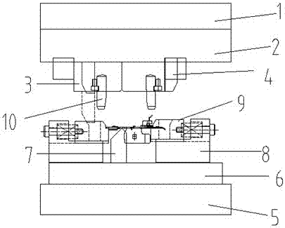
[0017] see figure 1 . It should be noted that the structures, proportions, sizes, etc. shown in the drawings attached to this specification are only used to match the content disclosed in the specification, for those who are familiar with this technology to understand and read, and are not used to limit the implementation of the present invention. Limiting conditions, so it has no technical substantive meaning, any modification of structure, change of proportional relationship or adjustment of size, without affecting the effect and purpose of the present invention, should still fall within the scope of the present invention. The disclosed technical content must be within the scope covered. At the same time, terms ...


PUM


Abstract

The invention provides a novel stamping inverted V-curved mold, which includes an upper mold frame plate and a lower mold frame plate, an upper mold fixing plate is arranged under the upper mold frame plate, and an upper concave template is arranged under the upper mold fixing plate , the upper concave template is provided with a punch, the punch can move horizontally, the lower mold base plate is provided with a lower mold backing plate, the lower mold backing plate is provided with a lower concave template, and the lower mold backing plate is provided with a lower concave template. Inserts are arranged on the concave template. On the one hand, the mold is designed with circular positioning columns and inserts to ensure the stability of the stamping product. On the other hand, after the stamping is completed, the burrs of the product face downward, so that when the robot is used to grab the product, the suction cup It can be directly sucked on the product, which is beneficial to the pick-up of the suction cup of the manipulator, avoiding the burrs of the product facing upward after the V-curve, and saving the step of turning the product after the stamping is completed.

Description

technical field [0001] The invention relates to a stamping inverted V-curved die. Background technique [0002] With the development of the stamping industry and the advancement of technology, the use of manipulators is very common. Now companies are also using manipulators instead of human production. When manipulators pick up products, they are basically sucked by suction cups. And for some products, the burr surface will be on the top after the stamping is completed, which makes the suction cup unable to suck the product when it sucks the product. In order to solve this problem, the common method is to burr the product in addition, which is equivalent to adding a process, reducing work efficiency and increasing work cost. [0003] Patent CN203778617U mentions an anti-product deformation mold with a synchronous forming bracket, which includes an upper mold and a lower mold, and is characterized in that: the upper mold includes an upper mold base, an upper backing plate, ...

Claims


Application Information

Patent Timeline
Patent Type & Authority Patents(China)
IPC IPC(8): B21D37/10B21D43/00
Inventor 陈惠东朱国凯
Owner 金牌模具(常熟)有限公司
Why Eureka
Try Eureka