Street lamp body

A lamp body and street lamp technology, applied in outdoor lighting, lighting and heating equipment, mechanical equipment, etc., can solve the problems of inconvenient replacement of light-emitting modules, poor stability of street lamps, and large force on the substrate, so as to avoid mutual interference and positional relationship Reasonable and balanced effect

Active Publication Date: 2015-11-18
HUZHOU QIUSHIGUANG ENERGY SAVING TECH DEV
View PDF8 Cites 0 Cited by
  • Summary
  • Abstract
  • Description
  • Claims
  • Application Information

AI Technical Summary

Problems solved by technology

However, it still has many deficiencies: First, the light-emitting module is fixed on the substrate, which makes the substrate bear a lot of force and has poor stability to the structure of the street lamp itself.
Second, the replacement of the light-emitting module requires the removal of the lampshade. During maintenance, it is very inconvenient to replace the light-emitting module

Method used


Image

  • Street lamp body
  • Street lamp body
  • Street lamp body

Examples


Embodiment 1

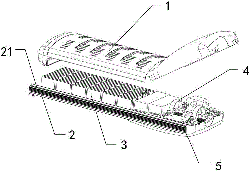
[0063] according to figure 1As shown, a lamp body of a street lamp includes: a lampshade 1, a lamp frame 2, a light emitting module 3, a power supply 4, and a lamp pole connecting portion 5. The lampshade 1, the light-emitting module 3, the power supply 4, and the light pole connection part 5 can be moved and adjusted in the installation assembly 21 before being fixed, and the lampshade 1, the light-emitting module 3, the power supply 4, and the light pole connection part 5 are all passed through the installation assembly. 21 is fixed on the lamp frame 2, wherein the lamp body of the street lamp contains one or more light emitting modules 3. By adjusting the positions of each part, different installation spaces are allocated for the light pole connecting portion 5, which is suitable for installation of various light poles. The adjustment of the position of the light-emitting module 3 brings different lighting effects to meet various lighting needs.

[0064] according to fi...

Embodiment 2

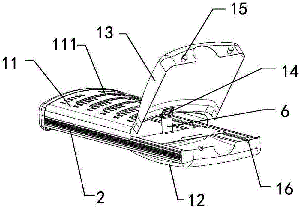
[0099] The difference from the first embodiment above is that the upper lampshade 11 is provided with an outer heat dissipation part 111, and the outer heat dissipation part 111 is provided with heat dissipation holes arranged in an array, and reinforcing ribs are also provided between the rows of some heat dissipation holes. The cooling holes are used to enhance the heat dissipation of the lamp body, and the reinforcing ribs are used to strengthen the structural strength of the lamp body.

Embodiment 3

[0101] The difference from the above-mentioned embodiment 1 is that, according to Figure 8 As shown, a reinforcement piece 6 is arranged between the lampshade 1 and the power connection plate 41, the upper end of the reinforcement piece 6 is connected with the spring hinge 14, and the lower end is connected with the power connection plate 41, so as to strengthen the overall structural strength of the lamp body.


PUM


Abstract

The invention relates to the field of illumination devices, in particular to a street lamp body. The street lamp body comprises a lampshade, a lamp frame, light emitting modules, a power source and a lamp pole connecting portion, and is characterized in that a mounting assembly is arranged on the surface of the lamp frame and enables the positions of the lampshade, the light emitting modules, the power source and the lamp pole connecting portion to be movably adjusted in the mounting assembly according to needs before fixing, and the lampshade, the light emitting modules, the power source and the lamp pole connecting portion are all fixed to the lamp frame through the mounting assembly. Different mounting spaces are distributed to the lamp pole connecting portion by adjusting the positions of all the components, so that the street lamp body is suitable for mounting of various lamp poles. The positions of the light emitting modules are adjusted, so that different illumination effects are achieved, and the street lamp body can meet various different illumination needs.

Description

technical field [0001] The invention relates to the field of lighting devices, in particular to a lamp body of a street lamp. Background technique [0002] At present, the energy shortage in the world has caused countries to attach great importance to energy-saving technologies, and countries have also increased their efforts in the rational and effective use of energy. Reflected in lighting is the continuous innovation and wide application of various new light sources. Among them, LED is more and more widely used in the field of lighting due to its low power consumption, high luminous efficiency, long life and high reliability, especially in the field of road lighting. Nowadays, LED street lamps begin to adopt a design structure in which light-emitting modules are installed on a substrate and then covered with a shell. For example, an LED street lamp disclosed in CN100480569 changes the lighting capability of the street lamp by changing the number of light-emitting modules...

Claims


Application Information

Patent Timeline
IPC IPC(8): F21S8/08F21V17/00F21V21/14F21W131/103
CPCF21S8/085F21V17/00F21V21/14F21W2131/103
Inventor 汪卫国陈卫沈旭初
Owner HUZHOU QIUSHIGUANG ENERGY SAVING TECH DEV
Why Eureka
Try Eureka