
Optical element and lighting device

An optical element and lighting device technology, applied in the field of optical elements, can solve the problems of difficulty in controlling the light distribution shape and glare index of large-angle panel lamps, and it is difficult to realize the lighting effect of the batwing light distribution curve, etc. The effect of uniform surface illumination and low UGR value

Pending Publication Date: 2015-11-18
OPPLE LIGHTING
View PDF6 Cites 0 Cited by
  • Summary
  • Abstract
  • Description
  • Claims
  • Application Information

AI Technical Summary

Problems solved by technology

[0003] There are many ways to control glare on the market, such as anti-glare rings commonly used in downlights and ceiling lights, grilles in grille lamp panels, etc., but it is difficult to control the light distribution shape and glare index of large-angle panel lamps At present, some low-glare panel lights on the market use the method of adding a prism plate to control glare. Due to the requirements of the overall weight of the prism plate, the influence of thickness on the optical efficiency, the limitation of production cost and the consideration of the appearance, the prism The total thickness of the plate is generally 2-3mm, and the height of the microstructure is often smaller
figure 1 and figure 2 Several common prism plates on the market are displayed. The prism plate with arc-shaped microstructure basically does not change the shape of the light distribution curve; It is difficult to realize the batwing light distribution curve to achieve low glare and uniform illumination of the working surface

Method used


Image

  • Optical element and lighting device
  • Optical element and lighting device
  • Optical element and lighting device

Examples


Embodiment Construction

[0031] The aforementioned and other technical contents, features and effects of the present invention will be clearly presented in the following detailed description of the embodiments with reference to the figures.

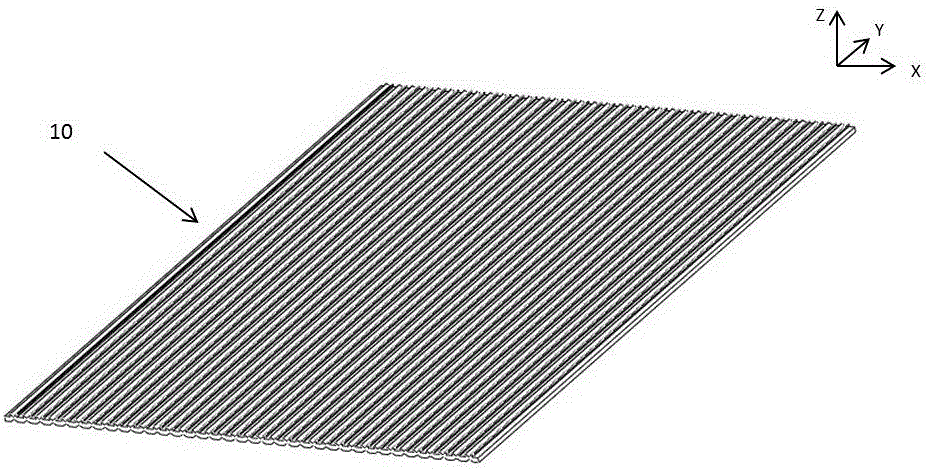
[0032] Combine below Figure 3 to Figure 7 , to describe the optical element of the present invention.

[0033] An optical element 10 includes a substrate 16 having opposite upper and lower surfaces 14 , 15 and a pair of sidewalls 17 , 18 . The upper surface 14 of the substrate is the light-emitting surface of the optical element, and a plurality of first microstructure units 12 are arranged at intervals on the upper surface. The first microstructure units 12 protrude from the upper surface 14, and the bottom 122 of the first microstructure unit is arranged on On the upper surface, the top end 121 of the protrusion of the first microstructure unit opposite to the bottom end has a groove structure. A plurality of second microstructure units 13 are arranged at in...


PUM


Abstract

The present invention provides an optical element. The optical element comprises a substrate which is provided with upper and lower surfaces and a pair of opposed side walls, the upper and lower surfaces are also opposed to each other, the upper surface of the substrate is a light exiting face and is provided with a plurality of raised first micro structure units, a bottom end of each first micro structure unit is arranged on the upper surface while a top end opposed to the bottom end is provided with a groove structure, the lower surface of the substrate is a light entering face of the optical element and is provided with a plurality of second micro structure units, and the second micro structure units sink from the lower surface towards the inside of the substrate. According to the optical element with the double-face micro structures, through coordination of the micro structure units of the upper and lower surfaces of the optical element, propagation directions of light rays are changed, bat wing light distribution is thus realized, and illumination of a working plane becomes uniform.

Description

technical field [0001] The invention relates to an optical element, in particular to an optical element with a microstructure and an illuminating device. Background technique [0002] When the brightness of a light source or object in the field of view is much greater than the brightness to which the human eye has adapted, people will feel dazzling, and this phenomenon is called glare. The national standard GB50034-2004 has clear regulations on glare and uniformity: the uniformity of illumination in the working room or work area should not be less than 0.7; libraries, reading rooms, offices, medical clinics and other places require a uniform glare value UGR< 19. [0003] There are many ways to control glare on the market, such as anti-glare rings commonly used in downlights and ceiling lights, grilles in grille lamp panels, etc., but it is difficult to control the light distribution shape and glare index of large-angle panel lamps At present, some low-glare panel lights...

Claims


Application Information

Patent Timeline
Patent Type & Authority Applications(China)
IPC IPC(8): G02B5/02F21V5/08
Inventor 李扬
Owner OPPLE LIGHTING
Learn More