
Reflector for illuminating light source and illuminating device comprising reflector

A technology for lighting devices and lighting sources, applied to lighting devices, components of lighting devices, reflectors, etc., can solve the problems of complex and expensive manufacturing process, achieve the effect of reducing UGR value and maintaining lighting intensity

Inactive Publication Date: 2018-04-27
NEONLITE DISTRIBUTION LTD
View PDF1 Cites 0 Cited by
  • Summary
  • Abstract
  • Description
  • Claims
  • Application Information

AI Technical Summary

Problems solved by technology

[0009] The technical solutions of the above two Chinese patent applications both involve the design of specific patterns on the lighting components. The production process of such technical solutions is complicated and expensive

Method used


Image

  • Reflector for illuminating light source and illuminating device comprising reflector
  • Reflector for illuminating light source and illuminating device comprising reflector
  • Reflector for illuminating light source and illuminating device comprising reflector

Examples


Embodiment Construction

[0056] While the invention has been illustrated and illustrated using preferred embodiments, the reflectors and scattering elements of the invention can be manufactured in many different configurations, sizes, shapes and materials.

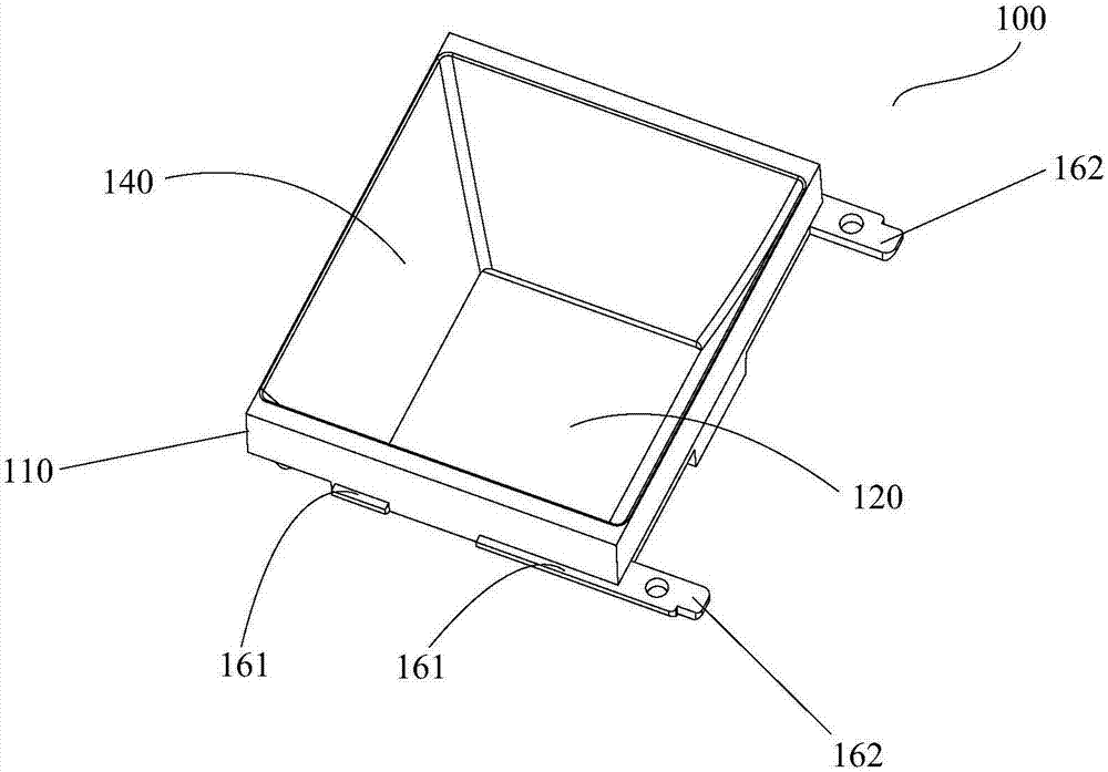
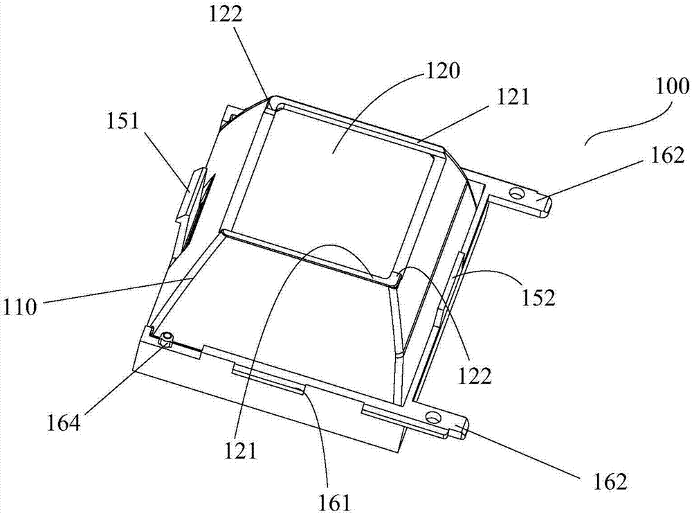
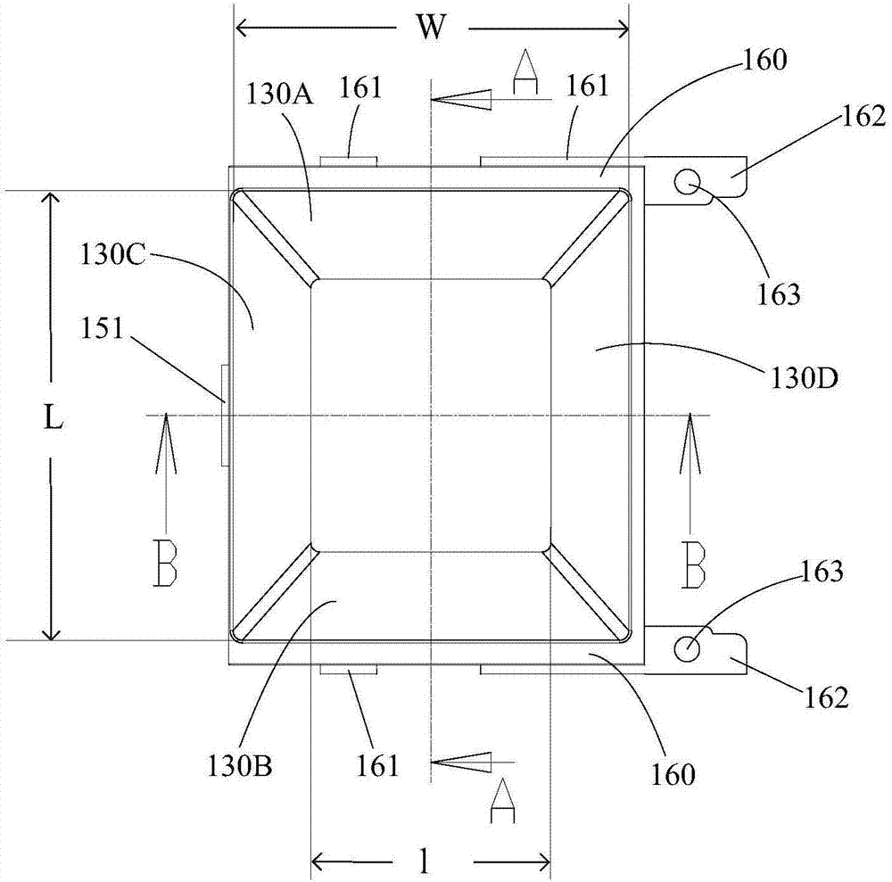
[0057] Referring now to the accompanying drawings, Figure 1A with 1B as well as Figure 2 to Figure 5 A reflector 100 constructed in accordance with a first preferred embodiment of the present invention is provided. In this embodiment, the reflector 100 includes a reflective body 110 , and the reflective body 110 includes a top opening 120 and a bottom opening 140 opened at the top and bottom thereof. In this embodiment, the reflective body 110 is surrounded by four side walls 130A, 130B, 130C, and 130D. The longitudinal section of the tetrahedron formed by the four side walls has a trapezoidal profile, wherein the bottom opening 140 is larger than the top opening. 120 large. In the tetrahedron, two opposite sidewalls 130A, 130B are arranged ...


PUM


Abstract

The invention provides a reflector for an illuminating light source. The reflector comprises a main reflecting body comprising reflecting side walls, a top opening and a bottom opening. The inner surface of each side wall is constructed as a reflecting paraboloid, wherein a parabola of the paraboloid has two end points and a parabola apex, the parabola apex is closer to the top opening instead ofthe bottom opening, and the height between the connecting line of the two end points of the parabola and the parabola apex is the parabola height H. The ratio h / L of the height h of each side wall tothe length L of the bottom opening ranges from 0.4 to 0.7, the ratio h / H of the height h of each side wall to the parabola height H ranges from 0.55 to 0.75, and the ratio h / l of the height h of eachside wall of the reflector to the length l of the top opening ranges from 0.3 to 0.55. The invention further provides an illuminating device comprising the reflector. By the aid of the illuminating device, the unified glare rating (UGR) can be reduced while the high illuminating output efficiency can be kept.

Description

technical field [0001] The invention relates to the field of lighting devices. More particularly, the present invention relates to a reflector for illuminating a light source and a lighting device including the reflector, which can achieve a low uniform glare value (UGR) while maintaining a high lighting output efficiency. Background technique [0002] As a solid-state light source with great development potential, LED has attracted more and more attention due to its advantages of long life, firm structure, low power consumption and flexible dimensions, and has gradually replaced traditional high-voltage halogen lamps in various applications. lighting field. However, the LED light source itself has the characteristics of high lumen output and small light-emitting area, which makes it easy to cause problems such as glare and large differences in illumination uniformity in the lighting space of the LED light source, resulting in a decrease in space comfort. Severe glare can ...

Claims


Application Information

Patent Timeline
Patent Type & Authority Applications(China)
IPC IPC(8): F21K9/20F21V7/22F21V17/14F21V19/00F21V29/503F21Y115/10
CPCF21V7/22F21V17/14F21V19/002F21V29/503F21V7/0083F21V7/06F21V7/09F21Y2103/00F21Y2115/10
Inventor 李荣德
Owner NEONLITE DISTRIBUTION LTD
Learn More