Vehicle brake hydraulic control equipment

A technology of vehicle braking and control equipment, applied in the direction of brakes, automatic starting devices, etc.

Active Publication Date: 2017-07-21
AUTOLIV NISSIN BRAKE SYST JAPAN CO LTD +1
View PDF1 Cites 0 Cited by
  • Summary
  • Abstract
  • Description
  • Claims
  • Application Information

AI Technical Summary

Problems solved by technology

The device disclosed in Patent Document 1 has a filter that limits changes in the output of the acceleration sensor used to calculate the gradient of the road surface

Method used


Image

  • Vehicle brake hydraulic control equipment
  • Vehicle brake hydraulic control equipment
  • Vehicle brake hydraulic control equipment

Examples


Embodiment Construction

[0026] Then, embodiments of the present invention will be appropriately described with reference to the drawings.

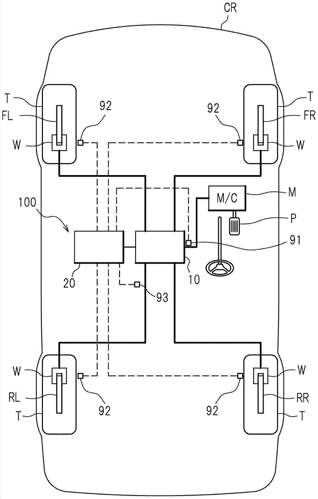
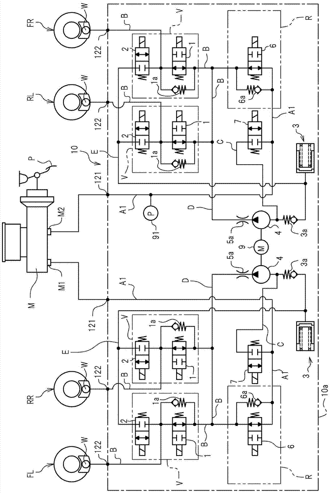
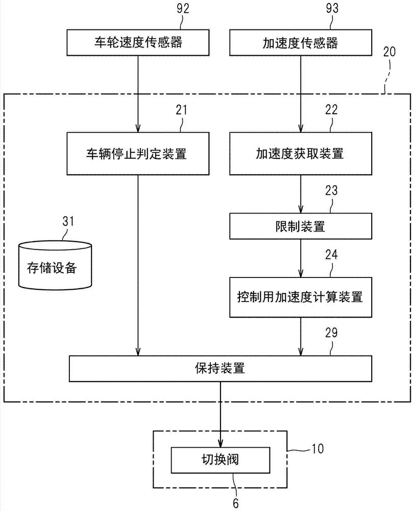
[0027] Such as figure 1 As shown, the vehicle brake hydraulic pressure control apparatus 100 appropriately controls the braking force applied to the wheels T of the vehicle CR. The vehicle brake hydraulic control apparatus 100 mainly includes a hydraulic unit 10 in which fluid lines and various components are provided; and a controller 20 which appropriately controls the various components in the hydraulic unit 10 .

[0028] The wheels T include wheel brakes FL, RR, RL, and FR, and each of the wheel brakes FL, RR, RL, and FR is provided with a wheel cylinder W that uses hydraulic pressure supplied from a master cylinder M as a hydraulic pressure source to Generate braking force. Master cylinder M and wheel cylinders W are connected to hydraulic unit 10 . The brake hydraulic pressure generated by the master cylinder M according to the depression force of the br...


PUM


Abstract

A vehicle brake hydraulic pressure control apparatus includes, as a controller 20, acceleration acquiring means 22 for acquiring an output value of an acceleration sensor detecting a front-rear direction acceleration of a vehicle, limiting means 23 for limiting the magnitude of the output value acquired by the acceleration acquiring means 22 within a predetermined limit value, a filter (control acceleration calculation means 24) limiting a change of a value output by the limiting means 23 in a predetermined direction, and holding means 29 for determining a holding pressure according to a value output by the filter and, based on the holding pressure, holding the braking force.

Description

technical field [0001] The present invention relates to a vehicle brake hydraulic pressure control device capable of maintaining brake hydraulic pressure when a vehicle is stopped. Background technique [0002] There is known a braking force maintenance control device for maintaining braking force when a vehicle is stopped (Patent Document 1). The device disclosed in Patent Document 1 has a filter that limits changes in the output of the acceleration sensor used to calculate the gradient of the road surface. In this structure, it is possible to suppress a change in the acceleration value due to a pitching motion which is a back-and-forth swing caused when the vehicle is stopped. [0003] In addition, the vehicle braking force maintenance control device determines the braking force to be maintained to stop the vehicle even on a slope from the filtered acceleration. [0004] Patent Document 1: JP-A-2009-202665 Contents of the invention [0005] technical problem [0006]...

Claims


Application Information

Patent Timeline
Patent Type & Authority Patents(China)
IPC IPC(8): B60T7/12B60T8/173
CPCB60T7/12B60T8/173B60T13/146B60T13/662B60T13/686B60T2201/04B60T2201/06B60T8/171B60T8/245
Inventor 木下贵嗣赤峰宏平小池正树
Owner AUTOLIV NISSIN BRAKE SYST JAPAN CO LTD
Why Eureka
Try Eureka