Supercharge Your Innovation With Domain-Expert AI Agents!

A kind of silk grinding machine and silk grinding method

A technology of a wire grazing machine and a wire feeding mechanism, which is applied in cleaning methods and appliances, chemical instruments and methods, cleaning methods using tools, etc., and can solve problems such as unsightly molding, poor wire feeding of welding wire 03, and pores

Active Publication Date: 2017-07-07
KUNSHAN HUICHENGXIN AUTOMATION TECH CO LTD
View PDF1 Cites 0 Cited by
  • Summary
  • Abstract
  • Description
  • Claims
  • Application Information

AI Technical Summary

Problems solved by technology

Although this welding wire cleaning device can wipe the welding wire on four sides and remove impurities on the surface of the welding wire, from figure 1 It can be seen from the figure that the first jig 0121 and the second jig 0122 used for wiping will not replace the wiping medium when wiping, that is to say, the impurities wiped from the welding wire 03 will remain on the wiping medium. When welding wire 03, these impurities will reattach to the next section of welding wire 03, which will cause welding defects such as poor wire feeding, unstable current, unsightly shape and even pores during welding.

Method used


Image

  • A kind of silk grinding machine and silk grinding method
  • A kind of silk grinding machine and silk grinding method
  • A kind of silk grinding machine and silk grinding method

Examples


Embodiment 1

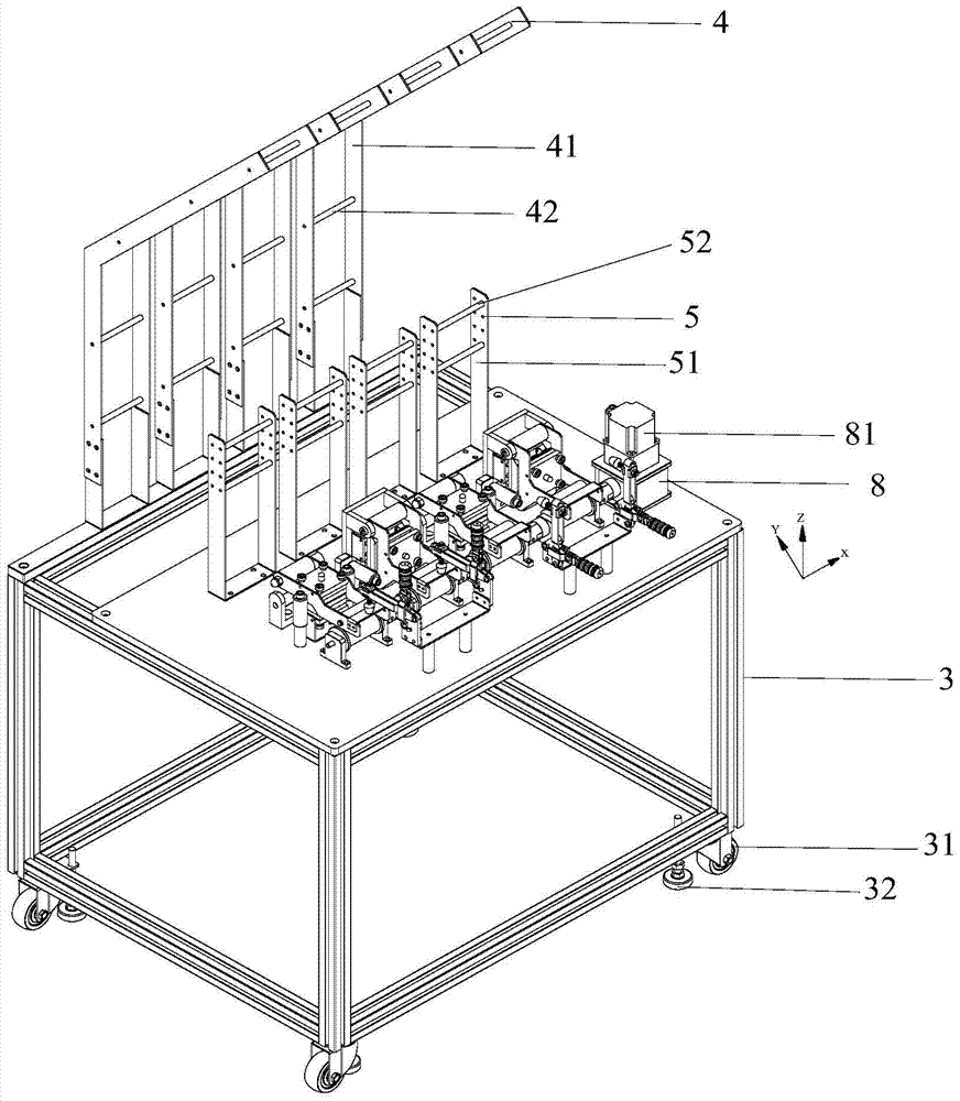
[0037] Please refer to image 3 , a kind of silk grating machine provided by the present invention is located on the frame 3, and includes several groups of grating device groups arranged in the first horizontal line, with the first horizontal line as the X axis, on the frame 3 table, with vertical The straight line on the first horizontal line is the Y axis, and a three-dimensional coordinate system including the X axis, Y axis, and Z axis is established with the vertical upward direction as the positive direction of the Z axis, and the XY plane is the table top of the rack 3. Please continue to refer to image 3 , the frame 3 includes two sets of grating device groups and arranged along the X-axis direction, each group of grating device groups includes two grating devices, also arranged along the X-axis direction, respectively horizontal grating device Device 1 and vertical grating device 2.

[0038] Preferably, in order to facilitate movement, the frame 3 is in the shape ...

Embodiment 2

[0069] The difference between this embodiment and Embodiment 1 is that among the two grating device groups, one grating device group is composed of two identical horizontal grating devices 1, and the other grating device group is composed of two identical vertical grating devices. The device 2 is composed, and the wiping effect of the welding wire 03 in the second embodiment is the same as that in the first embodiment.

Embodiment 3

[0071]The difference between this embodiment and Embodiment 1 is that, among the two grating device groups, the horizontal grating device 1 and the vertical grating device 2 of one grating device group are the same as those in Embodiment 1, and they are all arranged in the X-axis direction , please refer to Figure 10 , wherein the wiping direction of the welding wire 03 is the X-axis direction. The horizontal wiping mechanism 12 and the vertical wiping mechanism 22 of another wire wiping device group are arranged on a straight line forming an acute or obtuse angle with the X-axis direction, then another wire wiping device group will wipe the welding wire 03 as follows: Figure 11 As shown, the wiping direction of the welding wire 03 at this time is the direction of an acute angle or an obtuse angle with the X-axis direction, and the direction of an acute or obtuse angle with the Z-axis direction, so wiping the welding wire 03 from multiple directions in this way makes the wip...


PUM


Abstract

The invention provides a wire wiping machine. The wire wiping machine comprises a plurality of groups of wire wiping device units, each wire wiping device unit comprises a plurality of wire wiping devices, and each wire wiping device comprises a paper feeding mechanism, a wiping mechanism, a waste paper feeding mechanism and wire feeding mechanisms located at the two sides of the wiping mechanism, wherein the paper feeding mechanism, the wiping mechanism and the waste paper feeding mechanism form a first plane, the wire feeding mechanisms and the wiping mechanism are arranged in the first transverse line direction, and the first transverse line is intersected with the first plane. The invention further provides a wire wiping method of the wire wiping machine, therefore, a wire-shaped object is conveyed into the wiping mechanism to be wiped through the wire feeding mechanisms, an unused wiping medium enters the wiping mechanism from the paper feeding mechanism for wiping the thread-shaped object, and an used wiping medium is brought out of the wiping mechanism through the waste paper feeding mechanism. Therefore, the wire-shaped object can be wiped by the wiping medium while traveling, it is also guaranteed that the wiping medium used for wiping the corresponding wire-shaped object is unused every time, and the problem that the wire-shaped object is polluted on account of the reuse of the wiping medium is solved.

Description

technical field [0001] The invention relates to the field of filament treatment, in particular to a silk grating machine and a silk grating method. Background technique [0002] Welding wire is used as a filler metal or as a wire welding material for electrical conductivity. In gas welding and gas tungsten arc welding, the wire is used as the filler metal; in submerged arc welding, electroslag welding, and other gas-tungsten arc welding, the wire is both the filler metal and the conductive electrode. The surface of the welding wire is not coated with anti-oxidation flux. [0003] During the welding process, many impurities will adhere to the surface of the welding wire after transportation and storage. Not only that, but the current domestic welding wire production process causes many attachments to the surface of the welding wire. If it is welded immediately without treatment, the impurities and attachments will be in the It penetrates into the weld seam during welding, c...

Claims


Application Information

Patent Timeline
Patent Type & Authority Patents(China)
IPC IPC(8): B08B1/02B08B13/00
CPCB08B1/006B08B1/02B08B13/00
Inventor 范立江
Owner KUNSHAN HUICHENGXIN AUTOMATION TECH CO LTD
Features
  • R&D
  • Intellectual Property
  • Life Sciences
  • Materials
  • Tech Scout
  • Unparalleled Data Quality
  • Higher Quality Content
  • 60% Fewer Hallucinations
Learn More