
Install door lock without screws

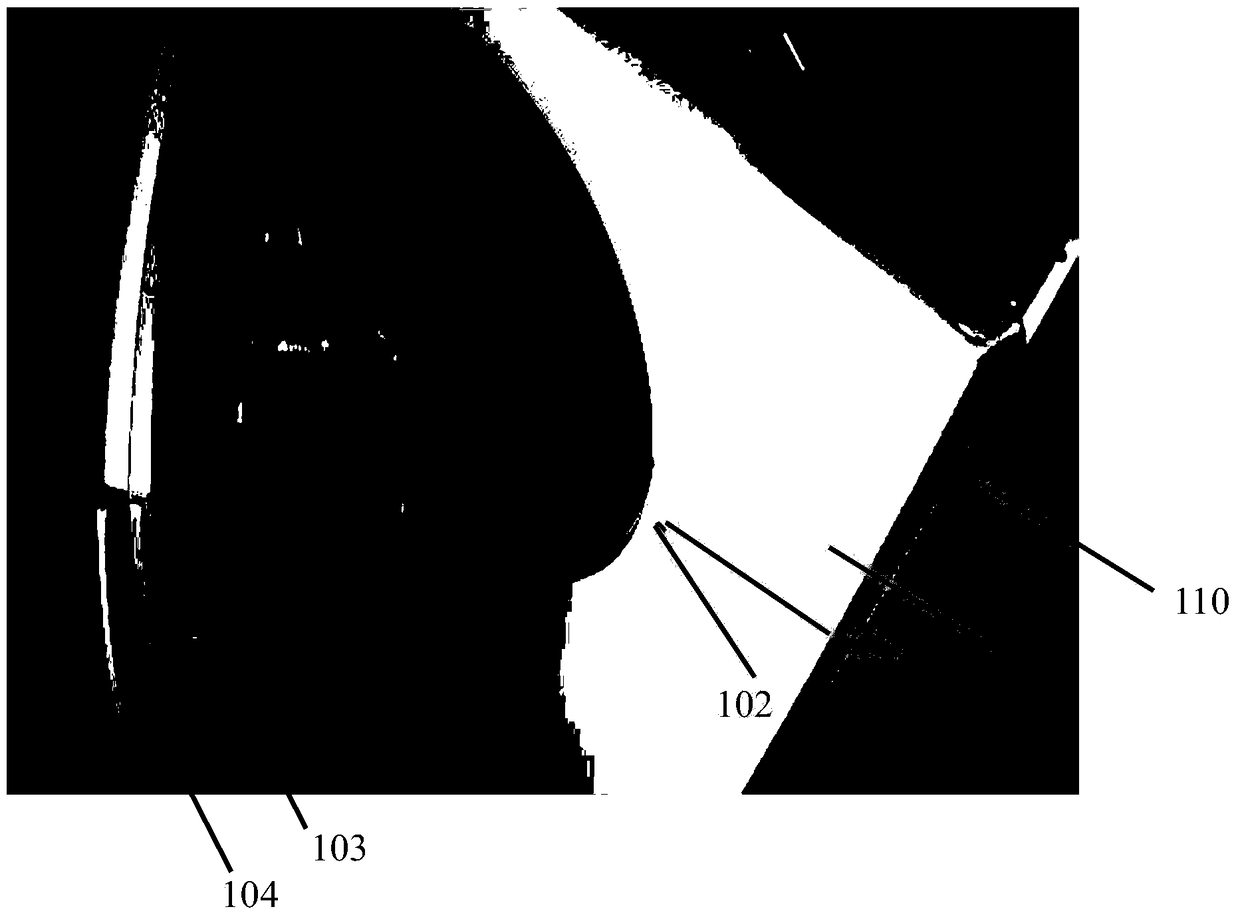
A door lock and door hook technology, which is applied in the field of electrical equipment door locks, can solve problems such as easy rusting of screws, time-consuming and labor-intensive door locks, and corrosion of washing machine panel holes, so as to prevent vibration from falling off and facilitate installation

Active Publication Date: 2018-12-07
ILLINOIS TOOL WORKS INC
View PDF8 Cites 0 Cited by
  • Summary
  • Abstract
  • Description
  • Claims
  • Application Information

AI Technical Summary

Problems solved by technology

[0003] However, the door locks currently on the market are fixed on the front panel of electrical equipment (such as a washing machine) by screws. There are certain defects in this method: the door lock of the washing machine is installed with screws, and the screws are easy to rust, and holes appear on the panel of the washing machine. Corrosion, door locks are not firm, etc. Second, it is time-consuming and labor-intensive to reinforce the door lock with screws, which is not conducive to improving production efficiency

Method used


Image

  • Install door lock without screws
  • Install door lock without screws
  • Install door lock without screws

Examples


Embodiment Construction

[0044] Various embodiments of the invention will be described below with reference to the accompanying drawings, which form a part hereof. It should be understood that although directional terms such as "front", "rear", "upper", "lower", "left", "right", "perpendicular", or "parallel" are used in the present invention Various example structural parts and elements of the present invention are described, but these terms are used herein for explanatory purposes only, based on the example orientations shown in the drawings. Since the disclosed embodiments of the present invention may be arranged in different orientations, these directional terms are for illustration only and should not be viewed as limiting. In the following drawings, the same reference numerals are used for the same components, and the similar reference numerals are used for similar components to avoid repeated descriptions.

[0045] figure 1 A schematic diagram of the position of the present invention installe...


PUM


Abstract

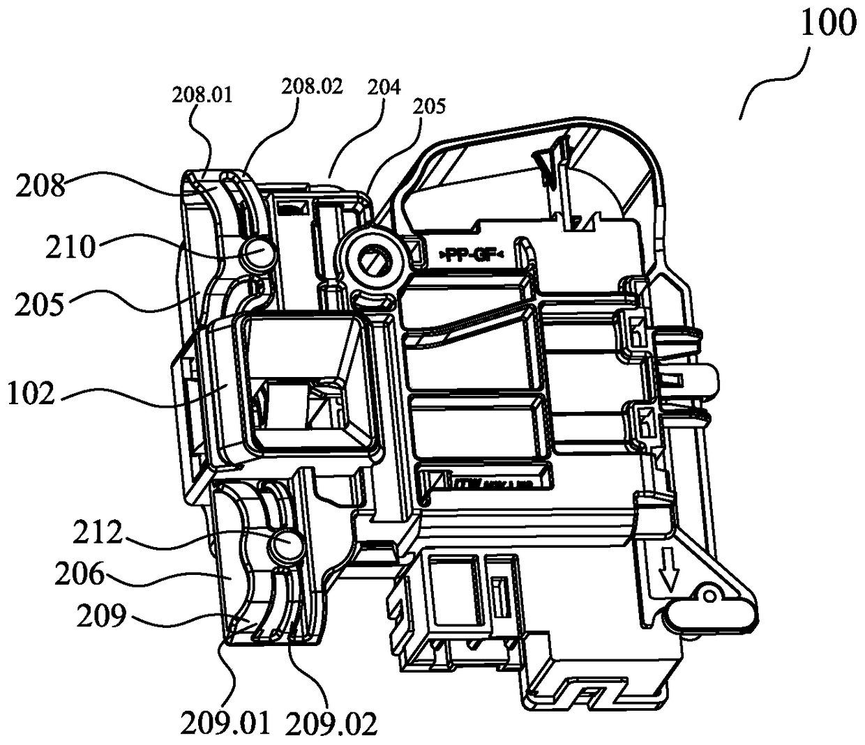
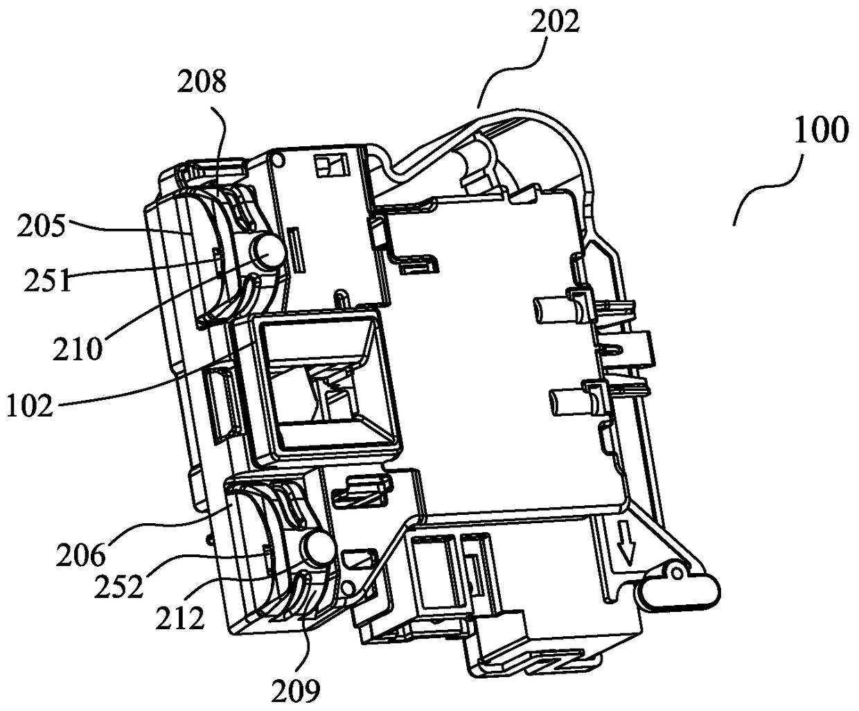
The invention provides a door lock base (114) and a door lock. The door lock base comprises a door hook hole (102), a first bottom plate (115), a second bottom plate (116), a first upward-protruding suspension support arm (108), a second upward-protruding suspension support arm (109), a first boss (111) and a second boss (112) which are arranged on the upper surfaces of the first suspension support arm and the second suspension support arm correspondingly, and a first resilient anti- disengagement elastic piece (151) and a second resilient anti-disengagement elastic piece (152) arranged under the first suspension support arm and the second suspension support arm. The two upward-protruding suspension support arms (108, 109) are adopted and the bosses on the support arms are clamped in holes of a front panel of an electrical device by means of the elastic deformation of the support arms, so that the door lock can be fixedly secured to the inner side of the front panel of the electrical device. The resilient anti-disengagement elastic pieces (251 / 252) are arranged under the bosses, so that the installation is facilitated and the bosses are prevented from moving downward after installation and are prevented from being disengaged from the holes because of vibration.

Description

technical field [0001] The invention relates to a door lock for electrical equipment, in particular to a mechanism for fixing the door lock on the inner side of the closing door of electrical equipment such as washing machines. Background technique [0002] At present, all electrical equipment needs to install a door lock mechanism with higher safety. Taking the large drum type washing machine as an example, the locking of the top plate (top plate) needs to be installed with a fixed door lock mechanism to prevent the large drum type washing machine from rotating at high speed when it is running (or still running due to inertia after it stops running). High-speed rotation), may cause harm to the human body. [0003] However, the door locks currently on the market are fixed on the front panel of electrical equipment (such as a washing machine) by screws. There are certain defects in this method: the door lock of the washing machine is installed with screws, and the screws are...

Claims


Application Information

Patent Timeline
Patent Type & Authority Patents(China)
IPC IPC(8): E05B15/00D06F37/42D06F39/14
Inventor 王栋轩
Owner ILLINOIS TOOL WORKS INC
Learn More