Touch electrode structure, touch screen and display device

A technology of touch electrodes and display devices, which is applied in the fields of electrical digital data processing, instruments, calculations, etc., and can solve the problems of difficult design of touch electrodes in display area/touch area, incomplete coverage of touch electrodes, poor linearity, etc.

Active Publication Date: 2015-11-25
BOE TECH GRP CO LTD +1
View PDF2 Cites 33 Cited by
  • Summary
  • Abstract
  • Description
  • Claims
  • Application Information

AI Technical Summary

Problems solved by technology

For example, it is difficult to design the touch electrodes on the edge of the display area / touch area
Since the edges of special-shaped display screens / touch screens are usually curved and polygonal, and the usual touch electrode patterns are rectangular, they cannot be well matched, resulting in the touch electrodes in the edge area of ​​the display area / touch area cannot completely cover the display. Edge of area / touch area
Incomplete or uneven coverage of the touch electrodes at the edge or corner of the touch screen, or beyond the display area, makes it difficult to guarantee the accuracy of touch control, resulting in inaccurate point reporting, or poor linearity and other defects

Method used


Image

  • Touch electrode structure, touch screen and display device
  • Touch electrode structure, touch screen and display device
  • Touch electrode structure, touch screen and display device

Examples


Embodiment 1

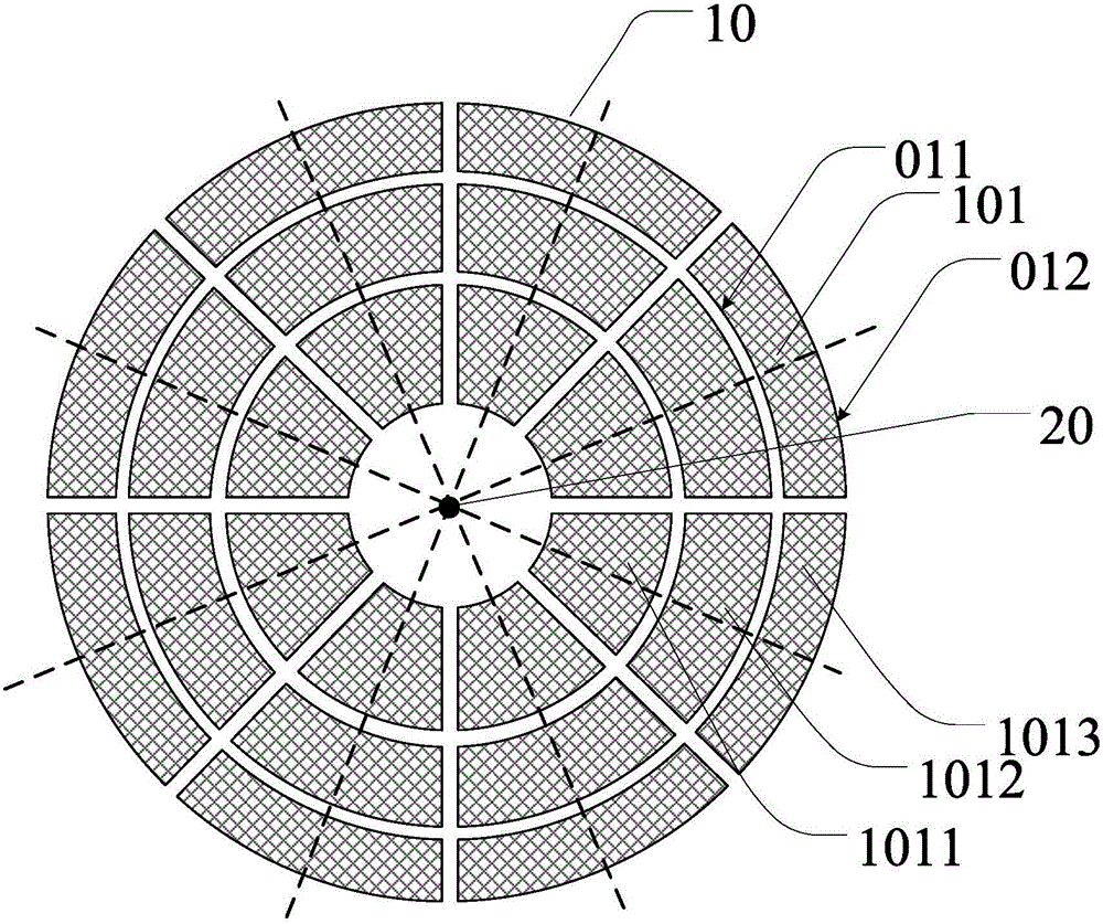
[0054] This embodiment provides a touch electrode structure, such as figure 2 As shown, a plurality of touch electrode groups 10 are included, and the plurality of touch electrode groups 10 are arranged around a center 20 . Each touch electrode group 10 includes a plurality of touch electrodes 101 . A plurality of touch electrodes 101 in each touch electrode group 10 are respectively arranged from a place close to the center 20 to a direction away from the center 20, and the size of the end 012 away from the center of each touch electrode 101 along the circumferential direction is larger than that of the touch electrode 101. The dimension of the end 011 near the center along the circumferential direction.

[0055] figure 2 8 touch electrode groups 10 are shown in , and each touch electrode group 10 includes 3 touch electrodes 101 . It should be noted, figure 2 It is only a schematic illustration, and the touch electrode groups and the number of touch electrodes included...

Embodiment 2

[0078] In Embodiment 1 and the examples described therein, each touch electrode structure may further include a central touch electrode 102 , and the central touch electrode 102 may be located at the center 20 .

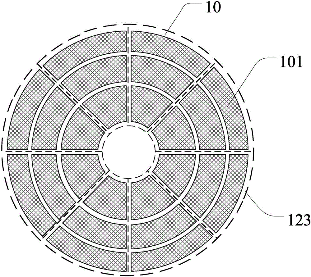
[0079] Such as Figure 5a As shown, the central touch electrode 102 and each touch electrode 101 in the plurality of touch electrode groups 10 cover a circular area.

[0080] Such as Figure 5b As shown, the central touch electrode 102 and each touch electrode 101 in the plurality of touch electrode groups 10 cover a fan-shaped area.

[0081] For example, the central touch electrode 102 and each touch electrode 101 in the plurality of touch electrode groups 10 may also cover a polygonal area.

[0082] It should be noted that the area covered by the central touch electrode 102 and the touch electrodes 101 in the plurality of touch electrode groups 10 is not limited to the above examples, and can be determined according to the number of touch electrode groups 10 and ...

Embodiment 3

[0087] In the touch electrode structure described in any of the above-mentioned embodiments and examples, for example, as Figure 6a , 6b , 6e, may also include a plurality of wires 111 (such as Figure 6e shown), each touch electrode 101 can be connected to each wire 111 through the transfer hole 151, wherein each touch electrode 101 in each touch electrode group 10 is electrically connected to each wire 111 for input / output signal . Figure 6a , 6b is a plan view of the touch electrode structure, Figure 6e for Figure 6a A-A' section view in . It should be noted that each touch electrode 101 can also be arranged on the same layer as each wire 111 and be directly connected to each other. There is no limit to this.

[0088] For example, if Figure 6a with Figure 6e As shown, a plurality of wires 111 are disposed on the base substrate 100 , an insulating layer 114 is disposed on the layer where the plurality of wires 111 are located, and a plurality of via holes 151 ...


PUM


Abstract

The invention discloses a touch electrode structure, a touch screen and a display device. The touch electrode structure comprises at least one touch electrode assembly, wherein the at least one touch electrode assembly is arranged around a center; each touch electrode assembly comprises a plurality of touch electrodes; the plurality of touch electrodes in each touch electrode assembly are independently arranged from a position near the center to the position far away from the center; and the circumferential dimension of the end part, which is far away from the center, of each touch electrode is greater than the circumferential dimension of the end part, which is near the center, of each touch electrode. The touch electrode structure can be used for non-rectangular (abnormal-shape) touch screens, can effectively and completely cover the non-rectangular touch screens according to requirements and avoids the phenomena of inaccurate report points, poor linearity and the like caused by that the touch electrodes on the edge or the corner of the touch screen can not be completely covered.

Description

technical field [0001] At least one embodiment of the invention relates to a touch electrode structure, a touch screen and a display device. Background technique [0002] As a brand-new human-computer interaction device, the touch screen greatly improves the efficiency and convenience of human-computer dialogue due to its direct, efficient, accurate, smooth, and stylish features, making entertainment and office more vivid and relaxing. Touch screens can be classified into resistive, capacitive, and infrared optical types. Among many touch technologies, capacitive touch is the most widely used, especially self-capacitive touch, which is widely used due to the lightness and thinness of the touch screen formed by it. [0003] The self-capacitive touch screen includes a touch electrode array made of a transparent conductive material (for example: ITO) on a base substrate, and these touch electrodes respectively form capacitance with the ground. When a finger touches the self-c...

Claims


Application Information

Patent Timeline
Patent Type & Authority Applications(China)
IPC IPC(8): G06F3/044
CPCG06F3/03547G06F3/0412G06F3/04164G06F3/0443G06F3/0448G02F1/13338G02F1/1343G06F2203/04103
Inventor 刘庭良高山黄炜赟
Owner BOE TECH GRP CO LTD
Why Eureka
Try Eureka