
Cutting cooling device

A cooling device and cooling wall technology, which is applied in the attachment devices of sawing machines, metal sawing equipment, maintenance and safety accessories, etc., can solve the problems of not being able to cool the blade and affecting the cutting quality of the product, so as to improve the cutting quality and ensure the cooling effect. Effect

Inactive Publication Date: 2015-12-02
SUZHOU KAIDE MICRO ELECTRONICS CO LTD
View PDF7 Cites 4 Cited by
  • Summary
  • Abstract
  • Description
  • Claims
  • Application Information

AI Technical Summary

Problems solved by technology

The existing cooling method cannot cool the blade well. Although most of the heat on the blade is dissipated, heat still accumulates at the edge of the blade, which affects the cutting quality of the product.

Method used


Image

  • Cutting cooling device
  • Cutting cooling device
  • Cutting cooling device

Examples


Embodiment Construction

[0018] In order to better understand the technical features, technical content and technical effects of the present invention, the accompanying drawings of the present invention will now be described in more detail in conjunction with the embodiments.

[0019] Below in conjunction with accompanying drawing and embodiment the patent of the present invention is further described.

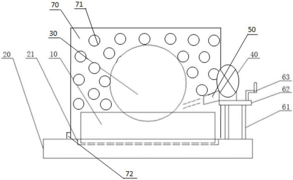
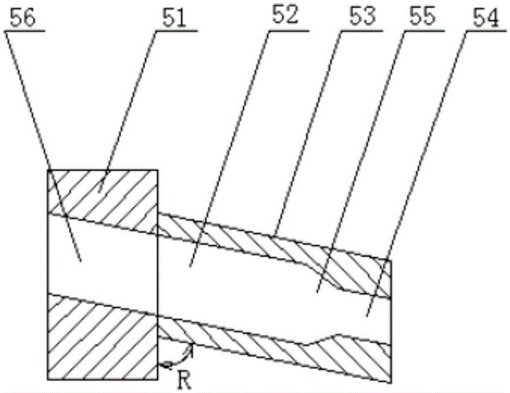
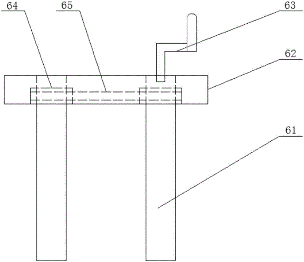
[0020] like Figure 1-3 As shown, a cutting cooling device includes a workbench 20 for placing the product 10 to be cut, and a blade 30 for cutting the product 10 on the workbench 20. For the convenience of the blade 30, the product 10 is cut accurately, A positioning groove 21 can be provided on the workbench 20 , and the product 10 is placed in the positioning groove 21 to position the product 10 . In order to completely cool the blade 30, the workbench 20 is provided with a blower fan 40 positioned on the same horizontal line as the blade 30 among the present invention, and the blower fan is provi...


PUM


Abstract

The invention provides a cutting cooling device which comprises a cooling wall and a fan. The cooling wall is a hollow cavity, fixed to a workbench and parallel to a blade. A plurality of water spraying openings communicated with the cavity are formed in the surface, close to the blade, of the cooling wall, a water inlet communicated with the cavity is formed in the bottom of the side face of the cooling wall, and a switch is arranged at the water inlet. The fan is arranged on the workbench and located on the same horizontal line with the blade, and an air nozzle facing the blade feeding direction in the blade cutting process is arranged on the fan and blows out an air column to the blade. The dual-cooling mode adopting air cooling and water cooling is adopted, not only can the blade be cooled, but also the blade can be washed.

Description

technical field [0001] The invention relates to a cooling device, in particular to a device for cooling a blade during cutting. Background technique [0002] In the cutting processing industry, the product is usually cut with a rapidly rotating blade. The friction between the blade and the product will cause the blade to heat up. According to the principle of thermal expansion and contraction, the heat accumulated on the blade will affect the product. It produces an impact and deforms the product, thereby affecting the cutting effect of the product. In order to ensure the cutting quality, it is usually necessary to cool the blade during the cutting process. The existing way to cool the blade is to install water spray pipes on the inside and outside of the blade, use the nozzle to spray fan-shaped spray, and cool the blade from both sides of the blade, and the fan-shaped spray from the nozzle acts on the blade. On both sides, the place where the blade really needs to be coo...

Claims


Application Information

Patent Timeline
Patent Type & Authority Applications(China)
IPC IPC(8): B23Q11/10B23D59/02
CPCB23Q11/10B23D59/02
Inventor 刘思佳
Owner SUZHOU KAIDE MICRO ELECTRONICS CO LTD
Learn More