A fast detection device for a dust shield and its working method

A technology of detection device and dust shield, which is applied to measurement devices, mechanical measurement devices, and mechanical devices, etc., can solve the problems of reduced product qualification rate, low efficiency, low measurement efficiency, etc., and achieves improved measurement efficiency and simple operation and measurement. , a wide range of effects

Active Publication Date: 2018-06-08
TAICANG SANYI HEATING & CHILLING PROJECT CO LTD
View PDF5 Cites 0 Cited by
  • Summary
  • Abstract
  • Description
  • Claims
  • Application Information

AI Technical Summary

Problems solved by technology

The motor dust shield is an important part of the motor after assembly and placed in the external environment where dust and impurities enter the motor and damage the motor. Therefore, the measurement of its size error is highly required in production. The existing measurement often uses manual comparison measurement. On the one hand The measurement efficiency is low, and multiple workers are required for assembly-line measurement. On the other hand, repetitive labor will inevitably lead to missed or false detections, which will reduce the product qualification rate (some companies increase the secondary measurement line, which will cost a lot and be inefficient). If rework It will increase the workload. If it is sold out of the factory, it will affect the reputation of the company. If it is directly transferred to the motor, there will be a major safety hazard. This is an urgent problem to be solved at present.

Method used


Image

  • A fast detection device for a dust shield and its working method
  • A fast detection device for a dust shield and its working method
  • A fast detection device for a dust shield and its working method

Examples


Embodiment

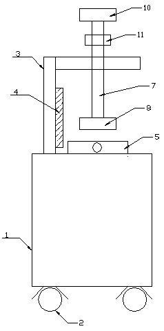
[0024] further as image 3 , Figure 4 and Figure 5 As shown, another aspect of the present invention provides a working method of a fast detection device for a dust shield. During detection, firstly, the dust shield to be measured is installed on the dust shield fixing seat 5, and then passes through the dust shield fixing seat 5. The thread-type adjusting bolt 6 set on the top will fix the dust shield to be measured, and then press down the mold base 8 with the same structure as the dust shield to be measured through the control handle 10, and finally observe the connection between the linkage rod 7 and the mold base 8. Scale scale 9, whether the error is within the allowable range, if so continue to the next process, if not screen out.

[0025] The rapid detection device of this structure has a reasonable design, convenient loading and unloading (the dust shield to be measured), and can replace the mold base 8 at the same time, which can meet the measurement requirements...


PUM


Abstract

The invention belongs to the technical field of motor accessory application, and specifically discloses a quick detection device for a dust board, and a working method of the quick detection device. The device comprises a vertical-type box seat, universal wheels disposed at the bottom of the vertical-type box seat, an L-shaped support disposed at a side of the upper part of the vertical-type box seat, a dust board fixed sat which is located at the center of the upper part of the vertical-type box seat and located below the L-shaped support, a linkage rod which is disposed at a side of the L-shaped support and is installed in a passing-through manner, a die seat which is connected with one end of the linkage rod, and a control handle disposed at the other end of the linkage rod. The device is reasonable in design, and meets the requirements of an assembly-line type measurement standard. Compared with the efficiency of a conventional measurement method, the measurement efficiency is improved by at least one time. In use, the dust board is placed on the fixed seat, and controls the downward moving of the linkage rod. The device is compared with a dust board die seat which is in the same structure as the dust board, is larger in size and has a ruler. Meanwhile, upper and lower dust board materials are more convenient. Because of the difference of a measurement product, the device can be disassembled, can replace the die seat, achieves multiple purposes, and is wide in application range.

Description

technical field [0001] The invention belongs to the technical field of production and application of motor accessories, and in particular relates to a quick detection device for a dust shield and a working method thereof. Background technique [0002] With the development of society and economy, the existing production equipment has been developing towards intelligence and automation, and various driving motors are indispensable components for mechanical equipment. Due to the different application occasions of different intelligent and automated mechanical equipment, the corresponding matching motors are also different, such as dust-proof motors, explosion-proof motors and dust-proof and explosion-proof motors. The assembly parts that make up various motors also have higher requirements, such as motor dust shields. The motor dust shield is an important part of the motor after assembly and placed in the external environment where dust and impurities enter the motor and damag...

Claims


Application Information

Patent Timeline
Patent Type & Authority Patents(China)
IPC IPC(8): G01B5/00
Inventor 林兰英
Owner TAICANG SANYI HEATING & CHILLING PROJECT CO LTD
Why Eureka
Try Eureka