Line outlet structure of internal water cooling phase-shifting transformer

A phase-shifting transformer, water cooling technology, applied in the direction of transformer/inductor coil/winding/connection, transformer/inductor cooling, etc., can solve the problem that the outlet structure cannot meet the requirements, the outlet structure is complex, and the number of outlet terminals is large. , to achieve the effect of convenient wiring, compact outlet structure and reduced volume

Inactive Publication Date: 2015-12-02
SHANGHAI NUCLEAR ENG RES & DESIGN INST CO LTD +1
View PDF5 Cites 0 Cited by
  • Summary
  • Abstract
  • Description
  • Claims
  • Application Information

AI Technical Summary

Problems solved by technology

[0002] At present, the outlet wires of the network side winding and the valve side winding of phase-shifting transformers on the market are respectively located on both sides of the iron core, and the outlet terminals of the valve side windings are bolts; There are circuit outlet terminals and waterway outlet terminals. The number of outlet terminals is large and the outlet structure is complicated. The outlet structure of the existing phase-shifting transformer cannot meet the requirements.

Method used


Image

  • Line outlet structure of internal water cooling phase-shifting transformer
  • Line outlet structure of internal water cooling phase-shifting transformer
  • Line outlet structure of internal water cooling phase-shifting transformer

Examples


Embodiment 1

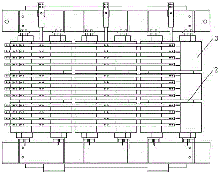
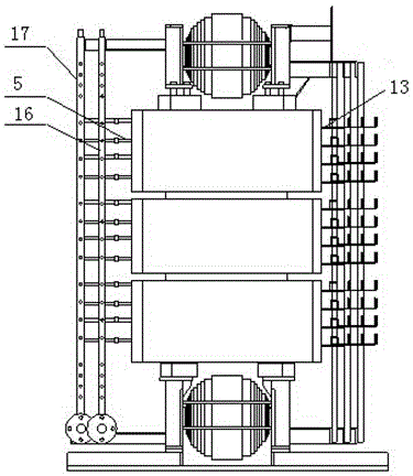
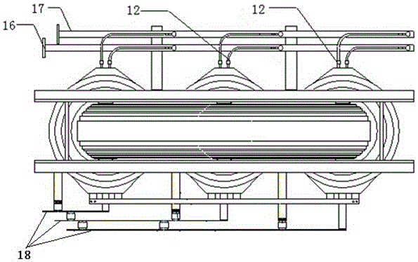
[0025] A water-internal cooling phase-shifting transformer outlet structure, including three-phase iron cores, each iron core is equipped with a plurality of valve-side windings 2 and a plurality of grid-side windings 3, and the valve-side windings 2 and grid-side windings 3 are sequentially arranged from top to bottom Arranged, the valve side winding 2 and the grid side winding 3 are all wound by a single hollow wire 0, and an insulating interval 14 is provided between the hollow wires 0, and the starting end 01 and the terminal 02 of the hollow wire 0 are both set There is a waterway outlet terminal 12; the start 01, terminal 02 and middle part 03 of the hollow wire 0 of the valve side winding 2 are provided with a circuit outlet terminal 13, and the start 01 and terminal 02 of the hollow wire 0 of the network side winding 3 are provided with Circuit outlet terminal 13. The circuit outlet terminals 13 of the valve side winding 2 and the network side winding 3 are located on ...

Embodiment 2

[0028] This embodiment is similar to Embodiment 1, furthermore, the valve-side winding 2 and the grid-side winding 3 are both wound by a plurality of parallel hollow wires 0 . The usage method of this embodiment is similar to embodiment 1.


PUM


Abstract

The invention belongs to the technical field of electric transformers, and particularly relates to a line outlet structure of an internal water cooling phase-shifting transformer. The structure comprises three phases of iron cores. Each iron core is sleeved with multiple valve side windings (2) and multiple line side windings (3). Both the valve side windings (2) and the line side windings (3) are sequentially arranged from top to bottom. The line outlet structure is characterized in that each valve side winding (2) or each line side winding (3) is formed by winding a single hollow wire (0) or multiple parallel-connected hollow wires (0), the start end (01) and the tail end (02) of each hollow wire (0) are each provided with a water path line outlet terminal (12), the start end (01), the tail end (02) and the middle (03) of each hollow wire (0) of each valve side winding (2) are each provided with a circuit line outlet terminal (13), and the start end (01) and the tail end (02) of each hollow wire (0) of each line side winding (3) are each provided with a circuit line outlet terminal (13). According to the line outlet structure of the internal water cooling phase-shifting transformer, the structure is compact, wiring is convenient, and the size of the internal water cooling phase-shifting transformer can be reduced.

Description

technical field [0001] The invention belongs to the technical field of power transformers, and more specifically relates to an outlet structure of a water-internal cooling phase-shifting transformer. Background technique [0002] At present, the outlet wires of the network side winding and the valve side winding of phase-shifting transformers on the market are respectively located on both sides of the iron core, and the outlet terminals of the valve side windings are bolts; There are circuit outlet terminals and waterway outlet terminals, the number of outlet terminals is large, and the outlet structure is complicated. The outlet structure of the existing phase-shifting transformer cannot meet the requirements. Therefore, it is necessary to provide a structure different from the outgoing line of the existing phase-shifting transformer to meet the outgoing line requirements of the internal water-cooled phase-shifting transformer. Contents of the invention [0003] In order...

Claims


Application Information

Patent Timeline
Patent Type & Authority Applications(China)
IPC IPC(8): H01F27/29H01F27/16
Inventor 顾国兴蔡定国马涛吴昊陆佩芳孙志强杨祥江黎剑锋唐金权
Owner SHANGHAI NUCLEAR ENG RES & DESIGN INST CO LTD
Why Eureka
Try Eureka