
Transformer low voltage large current outlet three-phase shared tank electric shielding structure

A low-voltage outlet, three-phase common box technology, applied in the field of transformer manufacturing, can solve the problems of poor effect, product overheating, complex shielding structure, etc., and achieve the effects of preventing local overheating, prolonging service life, and compact outlet structure

Active Publication Date: 2008-03-19
TBEA SHENYANG TRANSFORMER GRP CO LTD
View PDF0 Cites 0 Cited by
  • Summary
  • Abstract
  • Description
  • Claims
  • Application Information

AI Technical Summary

Problems solved by technology

[0002]At present, the existing large-capacity, high-voltage transformers generally use a single-phase single-rising socket lead-out structure for their low-voltage outlets, which makes the overall structure of the transformer large and not compact. Moreover, the shielding structure is complex and the effect is not good, resulting in overheating of the product, affecting the safe operation of the transformer and its service life

Method used


Image

  • Transformer low voltage large current outlet three-phase shared tank electric shielding structure
  • Transformer low voltage large current outlet three-phase shared tank electric shielding structure
  • Transformer low voltage large current outlet three-phase shared tank electric shielding structure

Examples


Embodiment Construction

[0017] The present invention will be described in further detail below in conjunction with the accompanying drawings.

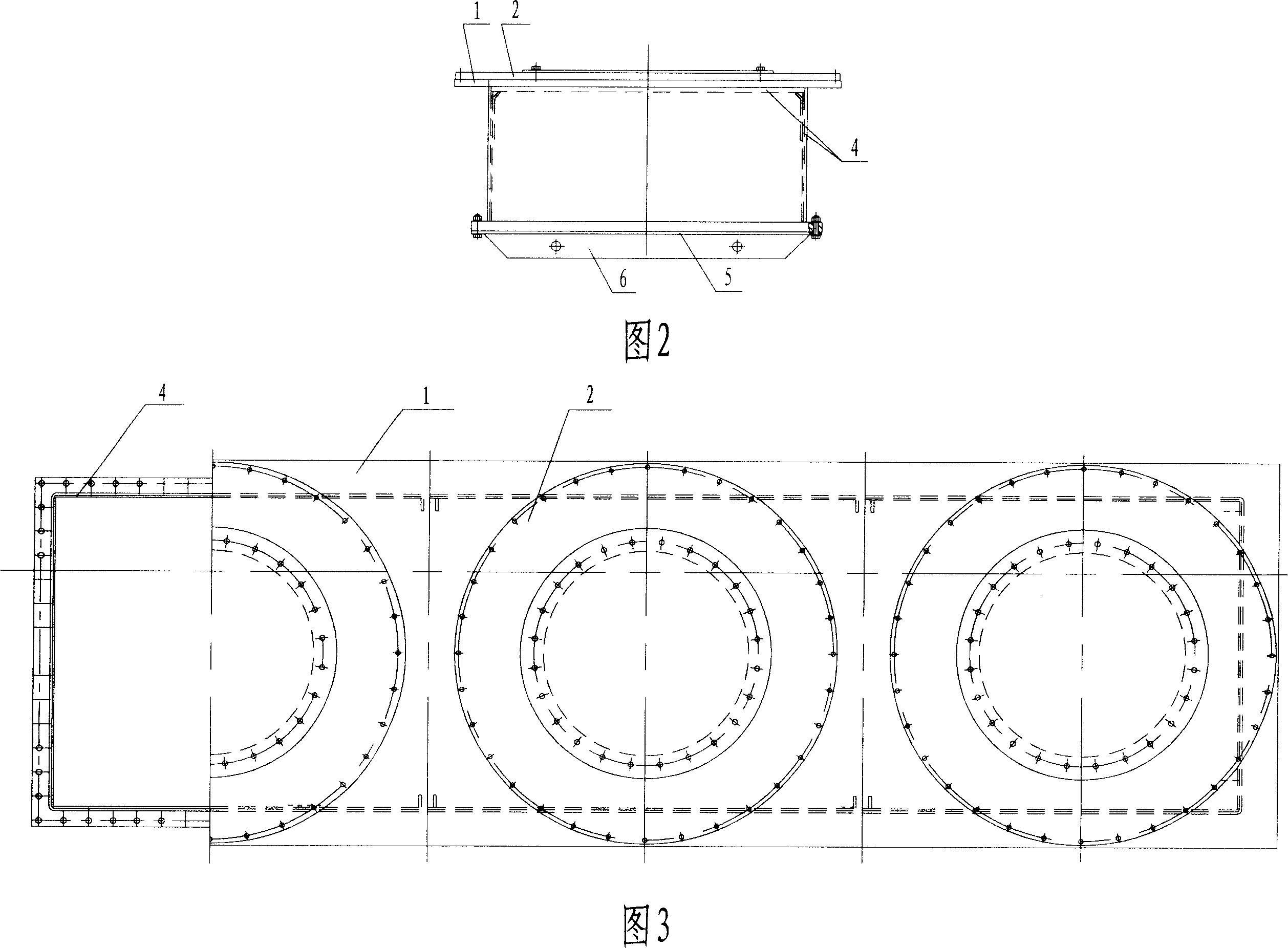
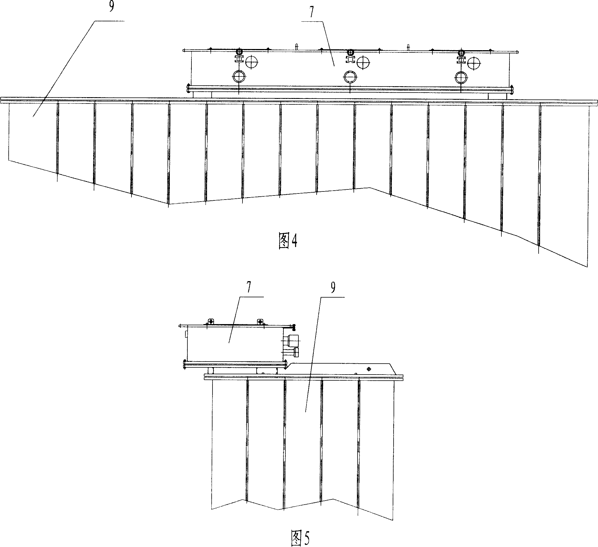
[0018] As shown in Fig. 4 and Fig. 5, the present invention is located above the low-voltage side of the transformer and connected with the transformer oil tank 9. As shown in Figures 1 to 3, the present invention includes a low-voltage riser 7, in which an electric shielding structure 4 is installed, and the three-phase low-voltage terminals of the transformer are inserted into the low-voltage riser 7, share a riser, and are drawn out from the upper part of the riser. . The low-pressure rising seat 7 is a box structure, the upper ends of its four walls are fixedly connected with the upper cover plate 1, and the lower ends are connected with a flange 8. In order to keep it stable when carrying the raised seat, a lower cover plate 5 is detachably installed on the flange 8 on the bottom surface of the raised seat, on which a plurality of corner plates 6 are fi...


PUM


Abstract

The invention belongs to the field of transformer fabrication and specifically relates to a three-phase-in-one-tank electric shield structure at the low-voltage outlet terminal of a high-capacity three-phase transformer, which comprises a low-voltage boosting seat, an electric shield means is arranged and three-phase low-voltage terminals of the transformer are all inserted inside the low-voltage boosting seat, sharing the same boosting seat, and then introduced outwards from the top thereof. The low-voltage boosting seat is structured like a box such that the top edges of the four walls of the box are fixedly connected with an upper cover and the bottom edges thereof are connected with a flange. The electric shield means is provided at the inner side of the four walls and on the inner wall of the upper cover. The three-phase low-voltage terminals of the transformer pass through the electric shield means on the inner wall of the upper cover and the flange. A bushing and a sealed bus flange are fixed on the top surface of the upper cover. The inventive three-phase outlet terminals share the same one boosting seat, has compact outlet structure and good electric shield effect, and can efficiently prevent the occurrence of local overheat. The loop of image current among phases is realized inside the three-phase-in-one-tank electric shield structure.

Description

technical field [0001] The invention belongs to the field of transformer manufacturing, in particular to a large-capacity, three-phase transformer low-voltage outgoing line three-phase common box electric shielding structure. Background technique [0002] At present, the existing large-capacity, high-voltage transformers generally adopt a single-phase single-rising socket lead-out structure at the low-voltage outlet end, which makes the overall structure of the transformer large and not compact, and the shielding structure is complicated and the effect is not good, resulting in overheating of the product and affecting the transformer. safe operation and its service life. Contents of the invention [0003] The purpose of the present invention is to provide an electrical shielding structure for three phases sharing a box at the outlet end of a transformer with good shielding effect. [0004] The purpose of the present invention is achieved through the following technical so...

Claims


Application Information

Patent Timeline
Patent Type & Authority Applications(China)
IPC IPC(8): H01F27/36
Inventor 孙勇赵刚
Owner TBEA SHENYANG TRANSFORMER GRP CO LTD
Learn More