Diagnostic device
A diagnostic device and signal technology, which is applied to measuring devices, uses electric/magnetic devices to transmit sensing components, instruments, etc., can solve the problem of the motor not outputting torque and speed, and achieve the effect of accuracy and soundness
- Summary
- Abstract
- Description
- Claims
- Application Information
AI Technical Summary
Problems solved by technology
Method used
Image
Examples
no. 1 approach
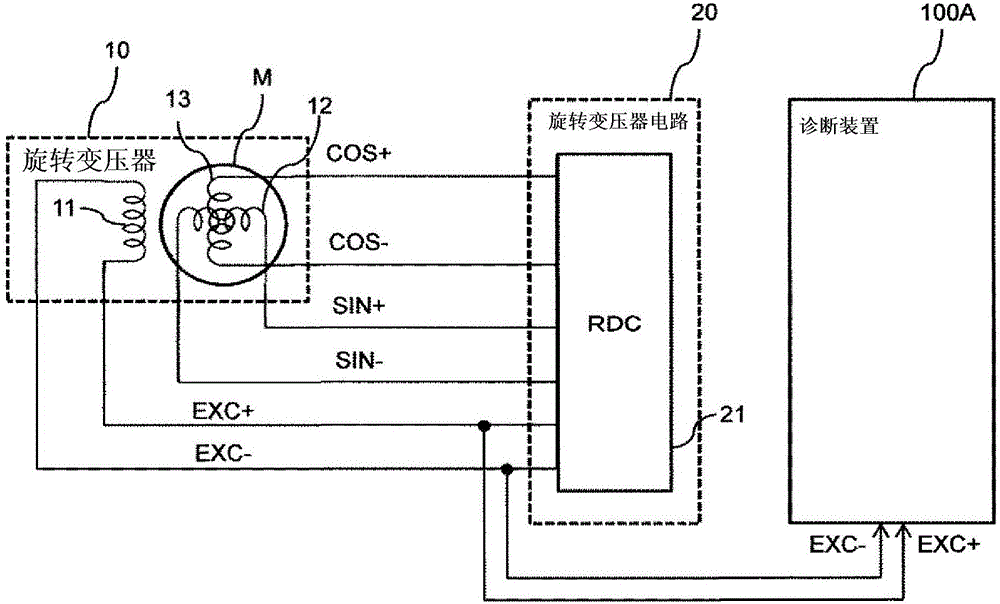
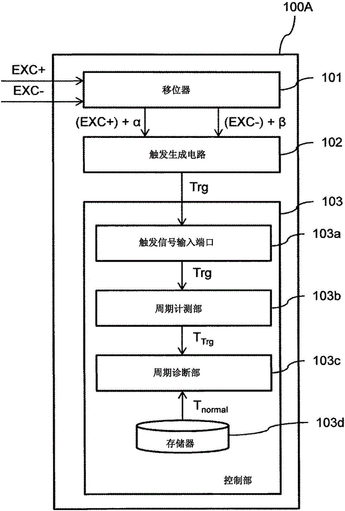
[0031] Below, use Figure 1 to Figure 5 The configuration and operation of a diagnostic device 100A according to the first embodiment of the present invention will be described. Diagnosis device 100A is a device that detects an abnormality in a resolver circuit that calculates a rotation angle θ of a motor for a vehicle.
[0032] First, use figure 1 An overall configuration of a resolver system including the diagnostic device 100A according to the first embodiment of the present invention will be described. figure 1 It is a configuration diagram of a resolver system including the diagnostic device 100A according to the first embodiment of the present invention.
[0033] The resolver system includes a motor M, a resolver 10, a resolver circuit 20, and a diagnostic device 100A.
[0034] The motor M is an electric motor that drives the vehicle.
[0035] The resolver 10 is a general angle sensor that detects the rotation angle θ of the motor M. As shown in FIG. The resolver 1...
no. 2 approach
[0067] next, so Figure 6 ~ Figure 8 , the configuration and operation of the diagnostic device 100B according to the second embodiment of the present invention will be described.
[0068] First, use Figure 6 , the overall configuration of the resolver system including the diagnostic device 100B according to the second embodiment of the present invention will be described. Figure 6 It is a configuration diagram of a resolver system including a diagnostic device 100B according to the second embodiment of the present invention. In addition, in Figure 6 in, right with figure 1 The same parts are assigned the same reference numerals.
[0069] exist Figure 6 in, with figure 1 In comparison, the output signals SIN+ and SIN− of the secondary coil 12 of the resolver 10 and the output signals COS+ and COS− of the secondary coil 13 of the resolver 10 are input to the diagnostic device 100B differently. In addition, it is also different in that an AB pulse (encoder pulse) corr...
no. 3 approach
[0091] Next, use Figure 9 ~ Figure 11 , the configuration and operation of the diagnostic device 100C according to the third embodiment of the present invention will be described.
[0092] First, use Figure 9 , the overall configuration of the resolver system including the diagnostic device 100C according to the third embodiment of the present invention will be described. Figure 9 It is a configuration diagram of a resolver system including a diagnostic device 100C according to a third embodiment of the present invention. In addition, in Figure 9 , right with Figure 6 The same parts are assigned the same reference numerals.
[0093] exist Figure 9 in, with Figure 6 In contrast, the RDC 21 is different in that an error signal Err is input to the diagnosis device 100C as a result of self-diagnosis.
[0094] Next, use Figure 10 , the configuration of a diagnostic device 100C according to a third embodiment of the present invention will be described. Figure 10 It...
PUM
 Abstract
Description
Claims
Application Information
 - R&D
- Intellectual Property
- Life Sciences
- Materials
- Tech Scout
- Unparalleled Data Quality
- Higher Quality Content
- 60% Fewer Hallucinations
Browse by: Latest US Patents, China's latest patents, Technical Efficacy Thesaurus, Application Domain, Technology Topic, Popular Technical Reports.
© 2025 PatSnap. All rights reserved.Legal|Privacy policy|Modern Slavery Act Transparency Statement|Sitemap|About US| Contact US: help@patsnap.com


