Waterway change-over valve and water purifier with waterway change-over valve

A technology for switching valves and water purifiers, applied to multi-way valves, valve devices, engine components, etc., which can solve problems such as difficult to determine, inconvenient to use, and increase hidden dangers of product leakage

Active Publication Date: 2015-12-09
ZHEJIANG QINYUAN WATER TREATMENT S T
View PDF7 Cites 2 Cited by
  • Summary
  • Abstract
  • Description
  • Claims
  • Application Information

AI Technical Summary

Problems solved by technology

However, when the water purification outlet valve is closed and the faucet valve is opened, the entire product, water pipes and waterway conversion device will bear water pressure, which requires higher safety and increases the hidden danger of product leakage
When letting the

Method used


Image

  • Waterway change-over valve and water purifier with waterway change-over valve
  • Waterway change-over valve and water purifier with waterway change-over valve
  • Waterway change-over valve and water purifier with waterway change-over valve

Examples


Embodiment 1

[0025] A water purifier with a waterway switching valve, including a water purifier and a waterway switching valve.

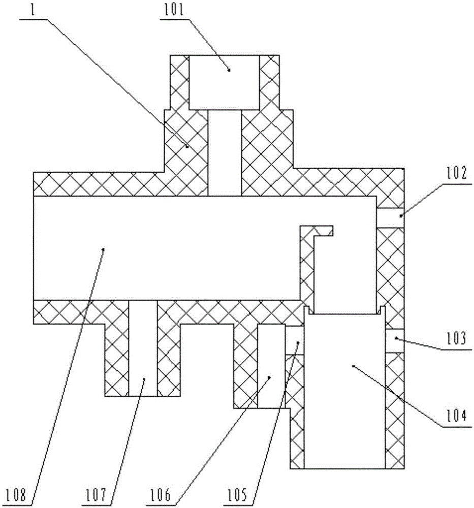
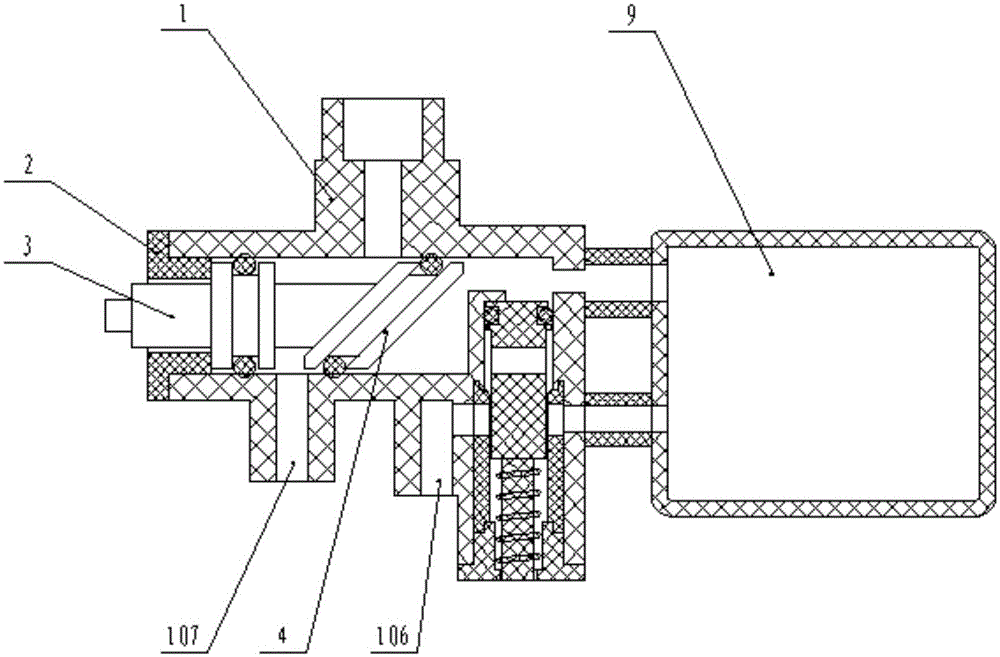
[0026] Wherein, the waterway conversion valve includes a valve body 1, such as figure 1 As shown, the valve body 1 is provided with a raw water inlet 101, an inner cavity 108 communicated with the raw water inlet 101, a first raw water outlet 102 and a second raw water outlet 107 communicated with the inner cavity 108, and the valve body 1 is also provided with There is an overflow valve cavity 104 communicated with the inner cavity 108, a filtered water inlet 103 and a filtered water outlet 106 communicated with the overflow valve cavity 104, and the filtered water inlet 103 and the filtered water outlet 106 are connected with the water purifier 9 at the same time. The water inlet and the water outlet are connected, and the raw water inlet 101 is connected with the tap.

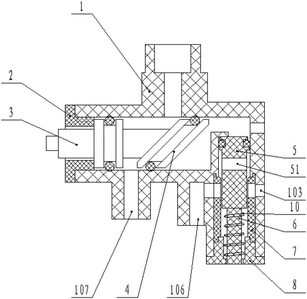
[0027] Such as figure 2 As shown, the reversing valve stem 3 extends into the inner ca...

Embodiment 2

[0031] Such as Figure 5 As mentioned above, the reversing spool 4 is relative to the attached Figure 4 Rotate 180°, at this time, the projection of the raw water inlet 101 along its axial direction is located in the lower bottom surface 402 of the valve core 4 of the reversing valve core 4, and the tap water flows into the inner cavity 108 from the raw water inlet 101, and then passes through the second inner cavity 108. The raw water outlet 107 flows out of the waterway switching valve. At this time, the upper end surface of the overflow valve core 5 is not subjected to water pressure, the overflow valve core 5 is located at the upper end of the overflow valve cavity 104 , and no water flows out from the filtered water outlet 106 .

Embodiment 3

[0033]Close the water tap connected to the waterway conversion valve, now no tap water flows into the raw water inlet 101, there is no water in the cavity 108, the overflow valve core 5 is located at the upper end of the overflow valve cavity 104, and no water flows out from the filtered water outlet 106.


PUM


Abstract

The invention relates to the field of water purification, and discloses a waterway change-over valve and a water purifier with the waterway change-over valve. The waterway change-over valve comprises a valve body (1), wherein a raw water inlet (101), an inner cavity (108) communicated with the raw water inlet (101), a first raw water outlet (102) and a second raw water outlet (107) are formed in the valve body (1); an overflow valve cavity (104) communicated with the inner cavity (108), a filtered water inlet (103) communicated with the overflow valve cavity (104) and a filtered water outlet (106) are also formed in the valve body (1); an overflow valve core (5) is arranged in the overflow valve cavity (104); a spring (10) is arranged at the lower end of the overflow valve core (5); and a flow channel (51) is formed in the overflow valve core (5). The waterway change-over valve solves the problem of water dropping of the waterway change-over valve in the prior art, which is caused by excess pressure; and meanwhile the waterway change-over valve can also control whether running water flows into a filter through rotating a reversing valve rod.

Description

technical field [0001] The invention relates to the field of water purification, in particular to a waterway switching valve and a water purifier with the waterway switching valve. Background technique [0002] For household water purifiers on the market, the water inlet of the product is connected with tap water, which can continuously supply water to the water purifier. Among these water purifier products, there is a type of water purifier placed on the kitchen countertop. In the filter element, the tap water is filtered, and the filtered clean water either flows out from the water outlet on the product; or the water flows back to the conversion device through the water pipe, and flows out from the water purification port of the conversion device; the current market Generally, two or three kinds of water can come out of the waterway conversion device, namely raw water, purified water and shower water. The direction of the water flow is changed by rotating the valve core ...

Claims


Application Information

Patent Timeline
IPC IPC(8): F16K11/10
CPCF16K11/10
Inventor 叶秀友梁建林彭开勤张春云
Owner ZHEJIANG QINYUAN WATER TREATMENT S T
Why Eureka
Try Eureka