
Lamp anti-disengagement light dimming mechanism capable of achieving inner and outer combined assembling

A combination of inside and outside, lighting technology, applied to the components of lighting devices, electric light sources, motor vehicles, etc., can solve the problems of increased space requirements for lighting fixtures, complicated manufacturing processes for plastic screws and bevel gears, and inconvenient lighting layouts.

Active Publication Date: 2015-12-09
JIANGSU WENGUANG VEHICLE ACCESSORIES
View PDF6 Cites 5 Cited by
  • Summary
  • Abstract
  • Description
  • Claims
  • Application Information

AI Technical Summary

Problems solved by technology

[0003] For the first method, after the product parts are assembled, often because the adjustment point is covered by other parts, it is impossible to effectively add anti-off screws or cards to form anti-off; for the second method, because the adjustment screw is pressed in from the outside of the lamp The bevel gear is fixed, and the screw forms a lateral force. The support of the screw to the mounting part is insufficient, and a larger structure needs to be added for auxiliary support, which increases the internal space requirement of the lamp, and is not convenient for the arrangement of lamps and internal parts of the vehicle.
Moreover, the manufacturing process of plastic screws and bevel gears is relatively complicated, and the material selection and manufacturing accuracy of related assembly structures are also high. If the fit is not good, there is a risk of the adjustment structure loosening and falling off.

Method used


Image

  • Lamp anti-disengagement light dimming mechanism capable of achieving inner and outer combined assembling
  • Lamp anti-disengagement light dimming mechanism capable of achieving inner and outer combined assembling
  • Lamp anti-disengagement light dimming mechanism capable of achieving inner and outer combined assembling

Examples


Embodiment Construction

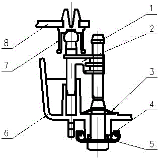
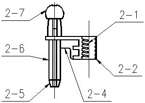
[0020] Depend on figure 1 It is well known that an anti-off dimming mechanism for lamps assembled internally and externally is composed of a gear screw 1, a ball head fixing buckle 2, a limit card 3, a sealing ring 4, an increasing slip gasket 5, a lamp housing 6, and a ball seat fixing buckle 7 , the adjusted workpiece 8, the gear screw 1 is fixed on the lamp housing 6 through the limit card 3, the slip pad 5 is arranged between the gear screw 1 and the lamp housing 6, the ball head fixing buckle 2 and the lamp housing 6 cooperate to realize the up and down guidance during thread adjustment; the ball seat fixing buckle 7 is arranged on the ball head fixing buckle 2, and the one side clamping foot of the ball seat fixing buckle 7 is connected with the adjusted part 8.

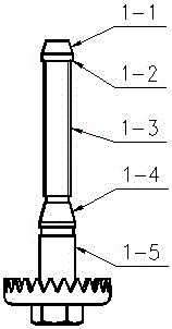
[0021] Depend on figure 2 It is a schematic diagram of the gear screw 1. The gear screw 1 is composed of chamfer I1-1, limit post 1-2, stud 1-3, chamfer II1-4, cylinder 1-5, and the outer diameter of limit p...


PUM


Abstract

Disclosed is a lamp anti-disengagement light dimming mechanism capable of achieving inner and outer combined assembling. The lamp anti-disengagement light dimming mechanism is composed of a gear screw (1), a ball bulb fixing buckle (2), a limiting clamping piece (3), a sealing ring (4), a slipping gasket (5), a lamp shell (6), a ball base fixing buckle (7) and an adjusted workpiece (8). The lamp anti-disengagement light dimming mechanism is characterized in that the bottom face of a limiting column (1-2) of the gear screw (1) makes contact with the top face of a plastic thread (2-1) of the ball bulb fixing buckle (2), so that the upper light dimming limit is achieved; the connecting section (2-4) of the ball bulb fixing buckle (2) makes contact with the top face of a rotation-prevention groove (6-6) of the lamp shell (6), so that the lower light dimming limit is achieved. The lamp anti-disengagement light dimming mechanism is stable in light dimming, easy to machine, large in range between the upper adjusting limit and the lower adjusting limit and applicable to an adjusting screw with no gear, and no clamping groove is formed in the adjusting screw so that light dimming with barb meshed fixing when the limiting clamping piece is pressed in can be achieved.

Description

technical field [0001] The invention belongs to the field of automobile lamp manufacturing and is used for manual dimming of the interior and exterior of automobile lamps, and relates to the installation, position limiting and adjustment methods of the dimming mechanism, as well as the guiding, anti-rotation and anti-off functions during the adjustment process. Background technique [0002] At present, the internal and external manual dimming mechanisms of automobile lamps generally have two methods: 1. The adjusting screw is assembled from the outside of the lamp and fixed by a limit card. The anti-off mechanism, or the anti-off screw or card is added to the top of the screw to form an anti-off; 2. The adjusting screw is assembled from the inside of the lamp and fixed by the bevel gear pressed in from the outside of the lamp. The external thread of this type of screw needs to be consistent with the internal thread of the fixing buckle. For snap-fit ​​assembly, the top of ...

Claims


Application Information

Patent Timeline
Patent Type & Authority Applications(China)
IPC IPC(8): F21S8/10F21V17/02F21W101/02F21W107/10
CPCF21V17/02
Inventor 徐兴荣李君胡继祖
Owner JIANGSU WENGUANG VEHICLE ACCESSORIES
Learn More